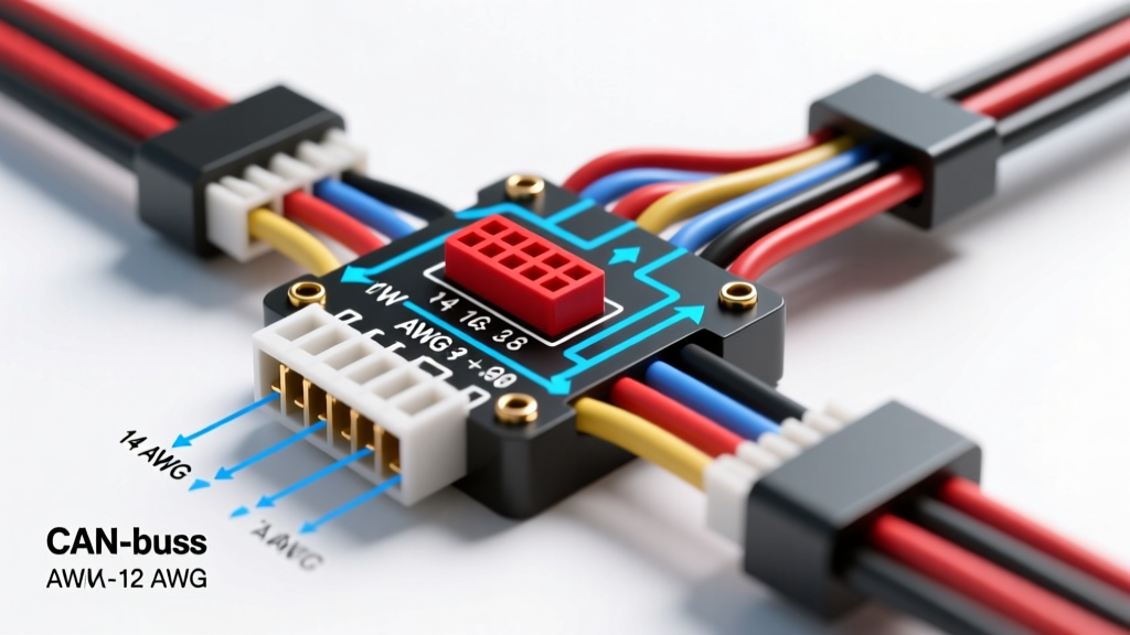
The Shift from PDF to Algorithmic Harness Mapping
Modern engine swaps, standalone ECU integrations, and complex OEM harness repairs demand absolute electrical precision. Relying on fragmented, multi-page PDF schematics often leads to mis-pinned connectors, ground loops, and catastrophic ECU failure. Enter the wiring diagram generator—a software-driven, algorithmic approach to harness design. By utilizing tools like WireViz or enterprise CAD netlist compilers, advanced automotive technicians can transition from manual guesswork to aerospace-level harness reliability. A wiring diagram generator ingests raw CSV or YAML netlists and automatically renders vector-accurate schematics, generates a precise Bill of Materials (BOM), and calculates total wire run lengths.
For high-performance platforms like the GM LS3 (utilizing the E38 or E92 ECU architecture), leveraging a wiring diagram generator is not just about drawing lines; it is about defining the electrical topology, managing electromagnetic interference (EMI), and ensuring proper terminal crimp profiles. This deep dive explores how to architect, generate, and validate a custom GM LS3 E38 engine harness using advanced diagram generation methodologies.
GM E38 ECU Connector Architecture and Cavity Mapping
The GM E38 ECU, standard on 2007-2010 LS3 and L99 engines, utilizes a 114-pin configuration split across three distinct connectors. When inputting data into a wiring diagram generator, you must define the exact connector housings and terminal types to ensure the generated BOM orders the correct TE Connectivity (formerly Tyco) components.
- X1 Connector (Black): 38-pin cavity. Primarily handles main power relays, ignition feeds, and high-speed CAN-bus communication. Utilizes GT150 and GT280 series terminals.
- X2 Connector (Gray): 38-pin cavity. Dedicated to high-current injector drivers and ignition coil control circuits. Requires robust 14-16 AWG wire for injector power feeds to prevent voltage drop under high duty cycles.
- X3 Connector (Black): 38-pin cavity. Houses low-voltage sensor inputs (MAF, MAP, TPS, O2), 5V reference feeds, and dedicated low-current sensor grounds.
When configuring your wiring diagram generator, defining the mating face versus the wire entry face is critical. The software will automatically mirror the pinout for the wire-entry side, preventing the most common harness-building error: building the connector backward.
Netlist Generation: LS3 E38 Pinout and Wire Gauge Matrix
Below is a foundational netlist matrix derived from GM OEM service data and cross-referenced with aftermarket Holley HP/EFI ECU manuals. This data structure is exactly what you would feed into a YAML-based wiring diagram generator to produce the schematic.
| Connector | Pin | OEM Wire Color | AWG | Circuit Function / Topology |
|---|---|---|---|---|
| X1 (Black) | 20 | Pink | 18 | Ignition 12V+ Feed (Relay Controlled) |
| X1 (Black) | 73 | Black/White | 12 | Powertrain Ground (High Current Block) |
| X1 (Black) | 54 | Dark Green | 18 | CAN High (GMLAN / SAE J1939 Bus) |
| X1 (Black) | 55 | Dark Green/White | 18 | CAN Low (GMLAN / SAE J1939 Bus) |
| X2 (Gray) | 1 | Dark Green | 18 | Injector 1 Control (Low Side Driver) |
| X2 (Gray) | 12 | Pink/Black | 14 | Injector Bank 1 Power Feed (12V+) |
| X3 (Black) | 11 | Light Blue | 18 | 5V Reference (TPS / MAP Shared) |
| X3 (Black) | 12 | Black/Red | 18 | Low Current Sensor Ground (Isolated) |
| X3 (Black) | 31 | Yellow | 18 | Crankshaft Position (CKP) Signal High |
| X3 (Black) | 32 | Yellow/Black | 18 | Crankshaft Position (CKP) Signal Low |
CAN-Bus Routing and GMLAN Topology in Generated Schematics
A sophisticated wiring diagram generator will not only map point-to-point connections but will also flag critical bus topologies. The LS3 E38 relies heavily on GMLAN (General Motors Local Area Network) and standard high-speed CAN for communication with the TCM (Transmission Control Module) and BCM (Body Control Module). According to SAE J1939 and automotive CAN standards, high-speed CAN operates at 500 kbps and is highly susceptible to Electromagnetic Interference (EMI).
When generating the harness layout, the software must enforce the following physical constraints:
- Twisted Pair Geometry: CAN High (Pin 54) and CAN Low (Pin 55) must be routed as a twisted pair with a minimum of 1 twist per inch (approx. 40 twists per meter) to cancel out common-mode noise.
- Termination Resistors: The generated BOM must include two 120-ohm, 1/4-watt resistors placed at the extreme physical ends of the CAN-bus network to prevent signal reflection.
- Isolation Routing: The diagram generator should flag if CAN-bus wires are routed parallel to high-voltage ignition coil feeds (X2 connector) for more than 6 inches, requiring a minimum 2-inch air gap or mu-metal shielding.
BOM Generation: Insulation and Terminal Selection
One of the most powerful features of an advanced wiring diagram generator is the automated Bill of Materials. For automotive engine bays, standard PVC wire is unacceptable due to heat degradation and chemical exposure. The generator must be configured to specify TXL (Thermoplastic Cross-Linked) or GXL wire insulation, which withstands continuous temperatures up to 125°C (257°F) and offers superior abrasion resistance.
Furthermore, the terminal selection in the BOM must match the wire gauge. The TE Connectivity GT150 terminals used in the E38 X3 connector require specific crimp profiles. Feeding a 20 AWG wire into an 18 AWG terminal cavity without a sealing plug or wire doubling technique will result in a failed pull-test and eventual moisture ingress. Open-source tools like WireViz allow engineers to define exact connector sub-components, ensuring the BOM includes the correct silicone cavity plugs and wire seals.
Galvanic Isolation and Sensor Grounding Strategy
A critical failure mode in custom LS3 harnesses is the mixing of high-current power grounds and low-current sensor grounds. The E38 ECU features internal galvanic isolation between the injector driver grounds (X2) and the 5V sensor reference grounds (X3). If a wiring diagram generator maps a shared ground wire for both a wideband O2 sensor and an ignition coil, the inductive kickback from the coil will induce voltage spikes on the 5V reference line, causing erratic fuel trims and phantom misfire codes.
The generated schematic must explicitly route 12 AWG ground wires directly from the cylinder heads to the ECU powertrain ground pins (X1-72, X1-73), while maintaining separate 18 AWG ground return loops for the MAP, TPS, and MAF sensors back to X3. The diagram generator will visualize these as distinct net nodes, preventing the builder from physically splicing them together in the harness loom.
Validating the Generated Schematic Against OEM Reality
Once the wiring diagram generator has produced the schematic and the physical harness is assembled, validation requires moving beyond simple multimeter continuity testing. Advanced diagnostics include:
- TDR (Time Domain Reflectometry): Used to detect micro-fractures or improper crimp compressions inside the ECU cavities without piercing the wire insulation.
- Oscilloscope CAN Validation: Probing the generated CAN High and CAN Low circuits to verify the differential voltage. CAN High should idle at 2.5V and rise to 3.5V, while CAN Low idles at 2.5V and drops to 1.5V. Any deviation indicates an incorrect termination resistor value or a short to the 12V injector power feed.
- Voltage Drop Testing Under Load: Using a carbon pile tester to simulate injector duty cycle while measuring the voltage drop across the generated X2 power feeds. A drop exceeding 0.2V indicates an undersized AWG selection in the BOM.
By treating the wiring diagram generator not just as a drawing tool, but as an electrical engineering compiler, technicians can eliminate harness-related failures and ensure the GM LS3 platform operates with OEM-level reliability in any chassis configuration.