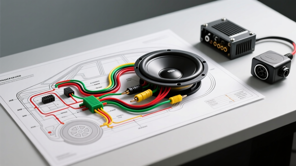
Understanding the Car Subwoofer Wiring Diagram
A comprehensive car subwoofer wiring diagram is the foundational blueprint for any high-fidelity mobile audio system. Unlike simple speaker replacements, integrating a subwoofer amplifier requires managing high-current DC power circuits, low-voltage analog audio signals, and precise impedance loads. Misinterpreting the schematic can lead to catastrophic failures, including melted wire harnesses, blown head unit traces, or clipped signals that destroy voice coils. This walkthrough dissects the universal amplifier wiring schematic, translating standard diagram symbols into actionable, vehicle-specific installation procedures.
Core Power and Ground Circuit Specifications
The power circuit in your car subwoofer wiring diagram dictates the physical thickness of the copper wire required to deliver current from the vehicle's alternator and battery to the amplifier's power supply capacitors. According to SAE International Standard J1127, battery cable sizing must account for both the continuous amperage draw and the total length of the wire run to prevent excessive voltage drop.
Amplifier Power Wire AWG Reference Chart
| Total Amplifier RMS Wattage | Recommended Power Wire (AWG) | Ground Wire (AWG) | Main Fuse Rating (ANL/Class-T) | Max Run Length (Under 16ft) |
|---|---|---|---|---|
| Up to 250W | 8 AWG | 8 AWG | 40 Amp | Standard |
| 250W – 500W | 4 AWG | 4 AWG | 60 Amp | Standard |
| 500W – 1000W | 1/0 AWG | 1/0 AWG | 120 Amp | Standard |
| 1000W – 1500W | 00 AWG (2/0) | 00 AWG (2/0) | 200 Amp | Standard |
| 1500W+ | 000 AWG (3/0) | 000 AWG (3/0) | 300+ Amp | Upgrade Alternator/Battery |
Crucial Installation Note: The main inline fuse must be installed on the positive power wire within 18 inches of the vehicle's positive battery terminal. This protects the vehicle's main electrical harness in the event the power wire chafes against the chassis and shorts to ground. Never rely solely on the amplifier's onboard fuses to protect the vehicle's wiring.
Step-by-Step Diagram Walkthrough: Head Unit to Amplifier
The signal and trigger portion of the car subwoofer wiring diagram originates at the head unit (source unit) and terminates at the amplifier's input and remote terminals.
RCA Signal Routing and EMI Prevention
RCA cables carry unbalanced, low-voltage analog audio signals (typically 2V to 4V RMS from preamp outputs). Because the signal voltage is so low, RCA cables act as antennas for Electromagnetic Interference (EMI). If routed parallel to the high-current power wire, the magnetic field generated by the alternator will induce a high-pitched whine into the audio signal that scales with engine RPM.
- Routing Rule: Run power and ground wires down the driver's side sill plate, and RCA signal cables down the passenger side sill plate.
- Crossover Rule: If the power and RCA cables must cross, they must intersect at a strict 90-degree angle to minimize inductive coupling.
- Shielding: Use twisted-pair, shielded RCA cables with a floating ground to reject common-mode noise.
Remote Turn-On (REM) Pinouts and Relay Wiring
The remote turn-on wire (typically an 18 AWG blue wire with a white stripe) signals the amplifier to power up when the head unit is turned on. Most aftermarket head units output 12V on this wire, but the internal circuit trace is usually limited to a maximum of 250mA (0.25 Amps).
If your wiring diagram includes multiple amplifiers, a digital signal processor (DSP), or a high-draw cooling fan, drawing more than 250mA from the head unit's remote lead will burn the internal PCB trace, permanently disabling the remote output. To solve this, the diagram must incorporate a standard 12V 30A SPST (Single Pole Single Throw) automotive relay:
- Terminal 86 (Coil +): Connect to the head unit's 18 AWG Blue/White remote wire.
- Terminal 85 (Coil -): Connect to a clean chassis ground.
- Terminal 30 (Common): Connect to a fused 12V constant or switched ignition source using 12 AWG wire.
- Terminal 87 (Normally Open): Connect to the REM terminals of all amplifiers using 14 or 16 AWG wire.
High-Level vs. Low-Level Signal Wiring Diagrams
Not all factory or aftermarket head units feature dedicated RCA preamp outputs. When integrating a subwoofer into a vehicle with a factory amplifier or a basic stereo lacking preouts, the wiring diagram must utilize a high-level signal path.
This requires a Line Output Converter (LOC). The LOC taps into the high-voltage speaker wires (typically 14 AWG to 16 AWG) running from the head unit or factory amp to the door speakers. The LOC steps down the high-level speaker signal (up to 40V in some premium factory systems like Bose or Harman Kardon) to a low-level RCA signal (under 4V) that the subwoofer amplifier can process. When wiring a LOC, ensure you maintain correct polarity: Left Front Positive (usually White) to LOC LF+, and Left Front Negative (White/Black stripe) to LOC LF-.
Subwoofer Enclosure Wiring: Impedance and Voice Coils
The final segment of the car subwoofer wiring diagram occurs inside the enclosure, connecting the amplifier's speaker terminals to the subwoofer's voice coils. Matching the final impedance to the amplifier's stable operating range is critical. As noted in Crutchfield's comprehensive subwoofer installation guides, mismatching impedance causes the amplifier to either overheat (if impedance is too low) or produce significantly less power (if impedance is too high).
Dual Voice Coil (DVC) 4-Ohm Subwoofer Configurations
For a single DVC 4-Ohm subwoofer, you have two primary wiring options depending on your amplifier's capabilities:
- Series Wiring (8-Ohm Final Load): Connect the amplifier's positive terminal to Voice Coil 1 Positive. Connect Voice Coil 1 Negative to Voice Coil 2 Positive using a jumper wire. Connect Voice Coil 2 Negative to the amplifier's negative terminal. This configuration is safe for almost all amplifiers but yields the lowest wattage output.
- Parallel Wiring (2-Ohm Final Load): Connect the amplifier's positive terminal to both Voice Coil 1 Positive and Voice Coil 2 Positive. Connect the amplifier's negative terminal to both Voice Coil 1 Negative and Voice Coil 2 Negative. This halves the impedance, allowing a 2-ohm stable monoblock amplifier to deliver maximum RMS wattage.
Common Wiring Faults and Multimeter Diagnostics
Even with a perfect car subwoofer wiring diagram, physical installation errors occur. Use a digital multimeter (DMM) to diagnose these common failure modes based on the Hertz Audio technical installation standards.
Troubleshooting Decision Tree
| Symptom | Probable Cause | Multimeter Diagnostic Test | Corrective Action |
|---|---|---|---|
| Alternator Whine (Pitch matches RPM) | Ground Loop / EMI Induction | Check AC voltage between amp ground and RCA outer shield. Reading > 0.05V AC indicates a ground loop. | Scrape ground point to bare metal. Ensure RCA and power wires are separated. Install a ground loop isolator if necessary. |
| Amp Power LED is OFF | Blown Main Fuse or No Remote Trigger | Measure DC voltage between amp REM terminal and amp Ground. Reading should be > 11V when HU is on. | Check inline battery fuse. Verify head unit remote lead output or test SPST relay wiring. |
| Amp goes into PROTECT mode under heavy bass | Voltage Drop or Impedance Short | Measure DC voltage at amp Power and Ground terminals during heavy bass hits. If voltage drops below 10.5V, wiring is insufficient. | Upgrade to larger AWG power wire, add a secondary battery, or check for stray speaker wire strands causing a short. |
| Subwoofer sounds weak or 'hollow' | Out of Phase Signal | Perform the 9V battery pop test on the subwoofer terminals to verify cone excursion direction matches the enclosure design. | Reverse the positive and negative speaker wires at the amplifier or subwoofer terminal block. |
By strictly adhering to the specifications outlined in this car subwoofer wiring diagram walkthrough, you ensure maximum power transfer, pristine signal integrity, and long-term reliability for your vehicle's electrical and audio systems.