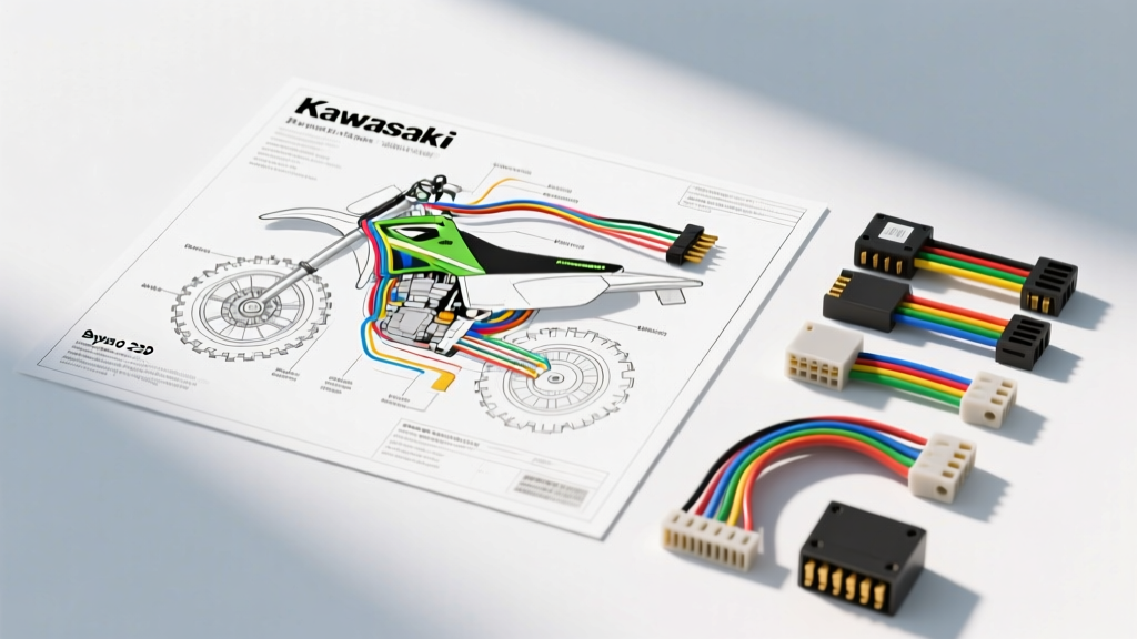
Decoding the KLF220 Electrical Architecture
The Kawasaki Bayou 220 (KLF220) is a legendary utility ATV, but its age means electrical gremlins are a common reality for owners. Unlike modern fuel-injected quads, the Bayou 220 relies on a relatively simple magneto-driven AC-CDI ignition system and a dual-purpose stator that handles both ignition excitation and lighting. When consulting a Kawasaki Bayou 220 wiring diagram, the most critical concept to grasp is the separation of AC and DC circuits. The headlights are often powered directly by the stator's AC lighting coil, while the taillights, brake lights, and horn rely on the DC rectified battery circuit. Misunderstanding this split is the number one reason DIY mechanics misdiagnose lighting and charging failures on this platform.
Before diving into the step-by-step troubleshooting flows below, ensure you have a digital multimeter (DMM) capable of measuring AC voltage, DC voltage, and resistance (Ohms). For advanced CDI testing, a Digital Volt Adapter (DVA) is highly recommended to read peak AC voltages.
Core Wiring Diagram Reference & Color Codes
Kawasaki adheres to a strict color-coding standard across its vintage ATV lineup. The table below outlines the primary wire colors you will encounter when tracing the main harness and stator outputs on the KLF220.
| Wire Color | Function / Circuit | Current Type | Typical AWG |
|---|---|---|---|
| Yellow | Lighting Coil Output (to Headlight/Regulator) | AC | 18 AWG |
| White/Red | Exciter Coil Output (to CDI) | AC (High Voltage) | 20 AWG |
| Blue | Pulse Pickup Coil Signal (to CDI) | AC (Low Voltage) | 22 AWG |
| Orange/Black | CDI Output to Ignition Coil Primary | DC (Pulsed) | 18 AWG |
| Black/White | Ignition Kill Switch / CDI Ground | DC (Ground) | 16 AWG |
| Red | Main DC Power (Battery to Fuse/Harness) | DC | 14 AWG |
| Black | Chassis Ground | DC (Ground) | 12 AWG |
Source Reference: Wire color standards verified against Haynes Kawasaki ATV Manuals and OEM KLF220 service documentation.
Step-by-Step Troubleshooting Flow
Flow 1: No-Spark Diagnosis (AC-CDI & Stator)
A no-spark condition on the Bayou 220 is rarely a failed CDI unit right out of the gate. More often, it is a grounded kill circuit or a failed stator coil. Follow this diagnostic tree:
- Step 1: Isolate the Kill Circuit (Black/White Wire). The KLF220 uses a "normally open" kill switch. When the switch is turned OFF, the Black/White wire grounds out, shorting the CDI and killing the spark. Disconnect the main harness plug near the CDI. Test for continuity between the Black/White wire and the chassis ground. If you have continuity with the key ON and the tether switch attached, you have a shorted kill switch or a pinched wire in the steering column.
- Step 2: Test the Pulse Pickup Coil (Blue Wire). Locate the stator connector (usually a 2-pin or 3-pin bullet connector near the left crankcase cover). Disconnect it and measure resistance across the Blue wire and its ground. Specification is typically 90 to 130 ohms at room temperature. An open reading (OL) means the pickup coil is internally broken and the stator must be replaced.
- Step 3: Test the Exciter Coil (White/Red Wire). This coil generates the raw AC voltage to charge the CDI's internal capacitor. Measure resistance; it should read between 320 and 480 ohms. If resistance is good, use a DVA adapter to check peak AC voltage while cranking. You need a minimum of 100V Peak to trigger the CDI. If voltage is low, the flywheel magnets may be demagnetized or the stator air gap is incorrect.
- Step 4: Verify Ignition Coil Primary. If the CDI is receiving power and a pulse signal, check the ignition coil. Primary resistance (Orange/Black to Black) should be 0.5 to 2.0 ohms. Secondary resistance (Spark plug cap to ground) should be 10,000 to 15,000 ohms.
Flow 2: Battery Charging System Failures
The Bayou 220 uses a simple shunt-style regulator/rectifier (R/R). If your battery is constantly dead, follow this flow:
- Step 1: Check Stator AC Output. Unplug the R/R connector. Start the engine and let it idle. Measure AC voltage between the Yellow (Lighting) and White (Charge) wires. At idle, you should see roughly 15-20V AC. Rev the engine to 3,000 RPM; voltage should climb to 35-50V AC. If AC voltage is low or missing on one leg, the stator windings are burnt.
- Step 2: Test the Rectifier Function. Set your DMM to Diode Test mode. Measure across the R/R pins. You should see a voltage drop of 0.4V to 0.6V in one direction, and OL (Open Line) in the reverse direction. If it reads 0.0V (short) or OL in both directions, the internal diodes are blown.
- Step 3: Verify DC Output. Reconnect the R/R. Measure DC voltage directly at the battery terminals while the engine is running at 2,500 RPM. The reading must be between 13.8V and 14.4V DC. If it exceeds 15V, the regulator's shunt circuit has failed and is boiling your battery.
Flow 3: The AC/DC Lighting Anomaly
Many owners mistakenly believe their Bayou 220 has a bad battery or rectifier when their headlights dim at idle but brighten when revving, while the taillights remain steady. This is normal operation.
- Headlight Circuit (AC): The headlight is wired directly to the stator's Yellow wire via the lighting switch. It runs on raw, unrectified AC power. Therefore, headlight brightness is directly proportional to engine RPM.
- Taillight/Brake Light Circuit (DC): These are wired to the Red (DC) circuit, powered by the battery and regulated by the R/R. They will remain steady regardless of RPM, provided the battery holds a surface charge.
- The Fix for AC Headlights: If you want steady LED headlights, you cannot wire them to the stock Yellow AC wire. You must install a full-wave rectifier, upgrade the stator, or wire a relay directly to the battery's DC circuit, ensuring you upgrade the main fuse from 10A to 15A to handle the constant DC draw.
Component Resistance & Voltage Specifications
Keep this reference chart in your toolbox when testing the KLF220 electrical system. All resistance values are measured at 68°F (20°C).
| Component | Test Points (Wire Colors) | Specification |
|---|---|---|
| Exciter Coil | White/Red to Ground | 320 - 480 Ω |
| Pulse Pickup Coil | Blue to Ground | 90 - 130 Ω |
| Ignition Coil (Primary) | Orange/Black to Black | 0.5 - 2.0 Ω |
| Ignition Coil (Secondary) | Plug Cap to Ground | 10k - 15k Ω |
| Stator Lighting Coil (AC) | Yellow to White (at 3k RPM) | 35 - 50V AC |
| Regulator/Rectifier Output | Red to Black (at 2.5k RPM) | 13.8 - 14.4V DC |
Connector Upgrades & Preventative Maintenance
The weakest link in the Kawasaki Bayou 220 wiring diagram is not the wire itself, but the OEM connectors. Kawasaki used standard unsealed bullet connectors for the stator and JST (Japanese Standard Terminals) for the harness blocks. Decades of mud, water, and pressure washing lead to galvanic corrosion, increasing resistance and causing voltage drops that mimic a failing stator.
Expert Repair Protocol:
- Eliminate Stator Bullets: Cut the OEM bullet connectors off the stator wires. Hard-solder the stator leads directly to the main harness using 18 AWG marine-grade tinned copper wire. Seal the splice with dual-wall adhesive-lined heat shrink. This single modification cures 80% of "no-spark" and "no-charge" issues on vintage KLF models.
- Dielectric Grease: Apply a liberal amount of silicone dielectric grease to all multi-pin plastic connectors, especially the CDI plug and the main harness bulkhead connector located behind the front grille.
- Ground Star-Washing: The main 12 AWG Black ground wire bolts to the crankcase. Remove this bolt, clean the aluminum mating surface with a wire wheel to bare metal, and reinstall using a star washer to ensure a vibration-proof, zero-resistance ground path.
For deeper schematic tracing and torque specifications on the flywheel puller and stator mounting bolts, always refer to the official Kawasaki Owner's Manuals archive or consult the community-driven wiring overlays at ATV Connection Forums. Proper diagnostics save you from throwing expensive, non-returnable CDI units at a simple $2 grounding issue.