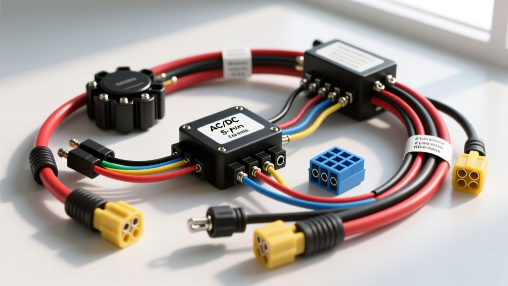
Decoding the Chinese 125cc Wiring Diagram PDF Landscape
When repairing or modifying off-road vehicles, scooters, or pit bikes powered by ubiquitous Chinese 125cc engines (such as the 152FMI, 154FMI, or CG125 clones), sourcing the correct schematic is only half the battle. Searching for a generic 'Chinese 125cc wiring diagram PDF' often yields conflicting information because manufacturers frequently alter wire color codes, connector types, and stator configurations mid-production. As an automotive electrical specialist, I have compiled this comprehensive product comparison and selection guide to help you identify your specific electrical architecture, choose the correct replacement wiring harness, and interpret the right schematic for your exact setup.
AC vs. DC Stator Systems: Which Diagram Do You Need?
The most critical fork in the road when selecting a wiring diagram for a Chinese 125cc engine is determining whether your stator powers an AC (Alternating Current) or DC (Direct Current) lighting system. Installing a DC harness on an AC stator will result in blown bulbs at high RPMs, while an AC harness on a DC system will leave your battery dead and your lights flickering.
| Feature | AC Stator System (Common on Pit Bikes) | DC Stator System (Common on ATVs/Scooters) |
|---|---|---|
| Headlight Power | Driven directly by stator (engine must run) | Driven by battery (works with key on, engine off) |
| Battery Requirement | Optional (can run without one) | Mandatory (acts as voltage buffer) |
| Stator Coil Resistance | Source Coil: 110-280 Ω; Lighting: 0.2-1.5 Ω | Single Output Coil: 0.5-2.0 Ω (High Output) |
| Rectifier Type | 4-Pin (AC Half-Wave) | 5-Pin or 6-Pin (Full-Wave DC) |
| Typical Wire Colors | Yellow (AC Light), White (AC Charge) | Yellow (AC to Rectifier), Red (DC 12V Out) |
Reference: For detailed stator testing procedures and resistance specifications, consult the ElectroSport Industries Technical Resources database.
CDI Unit Selection: 5-Pin vs. 6-Pin Configurations
Your wiring diagram must match your Capacitor Discharge Ignition (CDI) unit. Chinese 125cc engines primarily use either a 5-pin or 6-pin CDI. The physical connector is often a 6-pin Molex-style nylon block, but one cavity may be empty. Selecting the wrong harness plug will misalign the kill switch and trigger circuits.
Standard 5-Pin AC CDI Pinout (Most Common)
- Pin 1 (Ground): Green wire. Connects to chassis/engine block. Must be 16 AWG or thicker to prevent voltage drop.
- Pin 2 (Pickup Coil): Blue/White wire. Carries the trigger signal from the magneto rotor. Resistance should read 130-500 Ω.
- Pin 3 (Ignition Coil Feed): Black/Yellow wire. High-voltage trigger to the external ignition coil.
- Pin 4 (Source Power): Black/Red wire. 100V-200V AC feed directly from the stator source coil.
- Pin 5 (Kill Switch): Black/White wire. Grounds the CDI to halt spark. Connects to handlebar switch and ignition key.
DC CDI Variation
If your engine uses a DC CDI, Pin 4 will be a Red wire carrying 12V DC from the ignition switch rather than AC from the stator. If your PDF diagram shows a Red wire entering the CDI block, you have a DC ignition system and must select a harness with a DC-specific ignition circuit.
Evaluating Aftermarket Wiring Harness Replacements
When the OEM harness is brittle, corroded, or modified beyond repair, you must select a replacement. The market is flooded with 'Universal 125cc Harnesses' and 'Model-Specific Harnesses' (e.g., TaoTao DB14, SSR 125). Here is how they compare from an electrical engineering perspective.
Universal 125cc Harnesses
Universal harnesses are cost-effective but require significant splicing. They typically terminate in generic 2.8mm female spade connectors and lack specific ECU or sensor plugs. More concerningly, many budget universal harnesses violate SAE J1128 Low Tension Primary Cable standards by using undersized 20 AWG wire for main grounds. This causes severe voltage drops, resulting in weak sparks and dim headlights. If you choose a universal harness, you must upgrade the main battery feed and ground loops to 12 AWG copper.
OEM-Specific Replica Harnesses
Model-specific harnesses feature the exact JST or Molex connectors required for your voltage regulator, CDI, and stator. They utilize proper 16 AWG wire for lighting circuits and 12 AWG for the starter solenoid and main ground. While more expensive, they eliminate the need for crimp-splicing, which is the leading cause of parasitic draws and moisture ingress in off-road environments.
Regulator/Rectifier Selection and Wiring
The regulator/rectifier converts the stator's AC output into DC to charge the battery and regulates the voltage to prevent overcharging. Matching this component to your diagram is vital.
- 4-Pin Rectifier (AC Systems): Features one Yellow (AC input), one White (AC input/Lighting), and two Green (Ground) wires. Output is unregulated AC to the headlight and half-wave DC to the battery.
- 5-Pin Rectifier (DC Systems): Features two Yellow (AC input from stator), one Red (12V DC output to battery), and two Green (Ground). This full-wave bridge rectifier provides superior charging amperage, necessary for vehicles with electric start and auxiliary accessories.
Troubleshooting Common 125cc Electrical Faults Before Rewiring
Before tearing out your harness based on a wiring diagram PDF, verify the source components using a digital multimeter (DMM). Many 'harness failures' are actually failed stators or improper pickup coil gaps.
- Test the Pickup Coil: Disconnect the engine-side stator plug. Measure resistance between the Blue/White and Green wires. A reading outside 130-500 Ω indicates a failed pickup. Additionally, verify the physical air gap between the pickup sensor and the flywheel reluctor tab; it must be exactly 0.015 to 0.020 inches (0.38-0.51 mm).
- Test the Source Coil (AC CDI only): Measure between Black/Red and Green. Expect 110-280 Ω. An open circuit (OL) means the stator must be replaced, rendering a new wiring harness useless.
- Check for Ground Loops: Set your DMM to DC Volts. Place the red probe on the battery negative terminal and the black probe on the engine block while cranking. A reading above 0.2V indicates a poor engine-to-frame ground strap, a notorious issue on Chinese 125cc tubular steel frames where powder coating acts as an insulator.
For advanced diagnostic flowcharts and multimeter testing protocols, refer to the Haynes Motorcycle Electrical Manual.
Final Selection Checklist
To successfully utilize a Chinese 125cc wiring diagram PDF and select the correct parts, confirm the following: (1) Identify if your lighting system is AC or DC by checking if the headlight turns on without the engine running. (2) Count the active pins on your CDI and trace the power feed wire (Black/Red for AC, Red for DC). (3) Inspect your rectifier plug for a 4-pin or 5-pin configuration. (4) Select an OEM-specific harness over a universal kit to ensure proper 16 AWG / 12 AWG wire gauge compliance and weather-sealed connectors. By matching your physical components to the correct schematic variant, you will eliminate the guesswork and ensure a reliable, spark-ready 125cc electrical system.