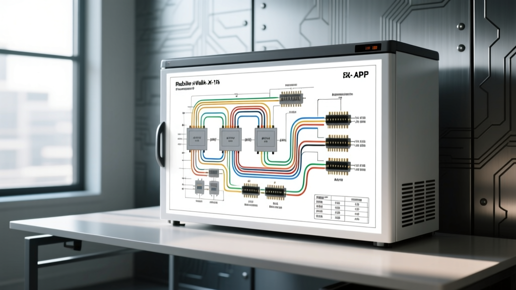
Adapting Commercial Walk-In Freezer Schematics for Mobile Applications
Technicians searching for a standard commercial walk-in freezer wiring diagram pdf often discover that mobile applications—such as step-van catering conversions, mobile medical supply trucks, and heavy-duty refrigerated trailers (reefers)—require significant electrical modifications. Unlike static brick-and-mortar installations tied to a stable municipal grid, mobile walk-in freezers must endure high-vibration environments, voltage fluctuations from vehicular alternators, and the complexities of DC-to-AC inversion or Auxiliary Power Unit (APU) integration.
This technical specification reference bridges the gap between standard commercial refrigeration schematics and SAE J1128 automotive wiring standards. Below, we detail the exact wire gauges, pin configurations, and contactor logic required to safely wire a mobile walk-in freezer system.
Primary Power Generation: Alternator and Battery Bank Integration
A mobile walk-in freezer typically requires a minimum of 3,500W to 5,000W of continuous power to run the compressor, evaporator fans, and control logic. This necessitates a high-output automotive alternator (e.g., Leece-Neville 280A or 320A) paired with a robust Lithium Iron Phosphate (LiFePO4) or AGM battery bank.
DC Bus Wiring Specifications
The connection between the vehicle battery bank and the pure sine wave inverter (or APU generator) is the most critical point of failure. Voltage drop in this DC circuit will cause the inverter to trigger low-voltage disconnects, shutting down the freezer compressor mid-cycle.
| Circuit Segment | Wire Gauge (AWG) | Max Length (One Way) | Insulation & Standard | Termination |
|---|---|---|---|---|
| Alternator to Battery Bus | 2/0 AWG | 8 ft | SAE J1128, Cross-linked | Heavy-duty ring terminal, 5/16 inch stud |
| Battery Bank to Inverter DC Input | 4/0 AWG | 6 ft | SAE J1128, Fine-strand | Anderson Powerpole SB175 or 3/8 inch lug |
| Inverter Ground to Chassis | 4/0 AWG | 3 ft | SAE J1128, Green/Yellow | Bonded to clean, bare chassis metal |
Note: Always use fine-strand, high-flex wire for mobile battery connections to prevent copper fatigue and strand breakage caused by vehicular vibration.
3-Phase Compressor Motor & Contactor Wiring
Most commercial walk-in freezer compressors (e.g., Copeland Scroll or Bitzer semi-hermetic) utilize 208/230V 3-phase power. In a mobile setup, this is supplied by a 3-phase inverter or a belt-driven APU generator. When referencing your walk-in freezer wiring diagram pdf, the L1, L2, and L3 line connections must be adapted for mobile vibration using lock-ring terminals rather than standard spade connectors.
AC Line Wiring & Phase Rotation
- L1 (Phase A): Black wire, 10 AWG (THHN/MTW rated for 600V). Connects to Contactor Terminal 1.
- L2 (Phase B): Red wire, 10 AWG. Connects to Contactor Terminal 3.
- L3 (Phase C): Blue wire, 10 AWG. Connects to Contactor Terminal 5.
- Ground (PE): Green wire, 10 AWG. Must be bonded directly to the compressor casing and the step-van chassis ground bus.
Phase Rotation Warning: Scroll compressors are phase-sensitive. If the compressor sounds abnormal or draws low amperage upon startup, the phase rotation is reversed. Swap the L1 and L2 connections at the contactor load side (Terminals 2 and 4) to correct rotation. Always verify with a digital phase rotation meter before sealing the junction box.
Evaporator Fan Integration: EC Motors and PWM Control
Modern mobile walk-in freezers utilize Electronically Commutated (EC) evaporator fans to reduce the AC load on the inverter. Unlike standard shaded-pole motors, EC motors require a PWM (Pulse Width Modulation) signal from the temperature controller to adjust fan speed based on the box temperature pull-down requirements.
- Power (L/N): 14 AWG (Black/White) supplying 120V AC to the motor internal driver.
- PWM Signal: 18 AWG Shielded (Yellow). Carries a 0-10V DC or 10kHz PWM signal from the Danfoss or Dixell controller.
- Tachometer Feedback: 18 AWG (Green). Returns RPM data to the controller to detect fan stalling.
If the EC motor fails to ramp up during the initial freeze-down, verify the PWM signal wire is not routed parallel to the 3-phase compressor lines, as Electromagnetic Interference (EMI) from the contactor switching can corrupt the low-voltage control signal.
Defrost Cycle and Evaporator Control Logic
The defrost circuit in a mobile walk-in freezer differs from static models due to the integration of 12V DC vehicle signals for ignition interlocks and engine-run requirements.
Defrost Timer and Heater Wiring
The defrost heaters (typically 1,500W to 2,000W) draw significant current. The control circuit utilizes a 12V DC signal from the vehicle ignition switch to prevent the defrost cycle from initiating while the vehicle engine is off, thereby preserving the house battery bank.
- Terminal 14 (Defrost Initiate): 14 AWG Orange wire. Receives 12V+ from the vehicle ignition relay.
- Terminal 15 (Defrost Terminate): 14 AWG White wire. Connected to the evaporator coil bi-metal thermostat (opens at 55°F).
- Heater Power (H1, H2): 12 AWG Brown wires routed through the defrost contactor to the evaporator heater rods.
Reefer Trailer & Step-Van Diagnostic Pinouts
When integrating a walk-in freezer into a towable reefer trailer or a detachable step-van box, a multi-pin connector is required to pass power and telemetry between the cab and the refrigeration unit. Below is the standard 12-pin mobile refrigeration connector pinout, adapted from OEM transport refrigeration guidelines.
| Pin | Function | Wire Color | AWG |
|---|---|---|---|
| 1 | Main DC Power (+12V) | Red | 8 |
| 2 | Main Ground | Black | 8 |
| 3 | Ignition Sense / Enable | Orange | 14 |
| 4 | CAN Bus High (J1939) | Yellow | 18 (Shielded) |
| 5 | CAN Bus Low (J1939) | Green | 18 (Shielded) |
| 6 | Alarm / Fault Output | Purple | 16 |
| 7 | Evaporator Fan High Speed | Blue | 14 |
| 8 | Defrost Request Signal | White | 14 |
Troubleshooting Mobile-Specific Electrical Faults
Mobile environments introduce unique failure modes not found in standard commercial walk-in freezer wiring diagrams. Use this decision tree to diagnose common mobile refrigeration electrical faults.
Symptom: Compressor Hard-Start Failure & Inverter Shutdown
- Cause 1: Excessive voltage drop on the DC battery-to-inverter cables during compressor Locked Rotor Amps (LRA) surge.
- Fix: Upgrade DC cables from 2/0 AWG to 4/0 AWG. Clean all chassis ground points to bare metal and apply dielectric grease.
- Cause 2: Undersized battery bank incapable of supplying the 400A+ transient surge.
- Fix: Add parallel LiFePO4 battery modules or install a soft-start module on the compressor to reduce LRA by 65%.
Symptom: Intermittent CAN Bus Communication Loss (Code 44)
- Cause 1: Fretting corrosion on the 12-pin diagnostic connector due to trailer flex and road vibration.
- Fix: Replace standard brass pins with gold-plated MIL-SPEC contacts. Apply NFPA 70 approved dielectric compound to the connector housing.
- Cause 2: Shield drain wire on J1939 CAN Bus cable improperly grounded at both ends, creating a ground loop.
- Fix: Terminate the shield drain wire at the ECU (Pin 4/5 shield) only; leave the trailer side shield floating.
Symptom: Rapid Evaporator Icing & High Head Pressure
- Cause: Evaporator fans are running at low speed or failing to start due to a broken tachometer feedback wire, causing the controller to default to a safe low-speed mode.
- Fix: Test the 18 AWG Green tachometer wire for continuity. Ensure the shield is grounded at the controller board to prevent EMI-induced false RPM readings.
Summary of Mobile Installation Best Practices
Translating a static walk-in freezer wiring diagram pdf into a mobile vehicular application requires strict adherence to automotive electrical standards. By utilizing SAE-rated fine-strand wiring, securing all terminations against vibration, and properly sizing the DC bus for high-amperage compressor surges, technicians can ensure reliable, food-safe or medical-grade mobile refrigeration across any transit route.