Introduction to Electric Water Pump Wiring Systems
As automotive thermal management evolves, mechanical belt-driven pumps are rapidly being replaced by Electric Water Pumps (EWPs). Whether you are diagnosing a BMW N55 auxiliary coolant pump, servicing a Ford EcoBoost electric auxiliary pump, or installing an aftermarket Davies Craig EWP150, interpreting the correct wiring diagram for a water pump is critical. Unlike simple 12V DC motors, modern OEM EWPs rely on Pulse Width Modulation (PWM) or Local Interconnect Network (LIN) bus signals to dictate flow rates based on real-time engine load and coolant temperatures. This guide provides a comprehensive cost and tool requirements analysis for professionals and advanced DIYers tackling EWP circuit diagnostics, harness fabrication, and system integration.
Decoding the Wiring Diagram: Water Pump Circuit Architecture
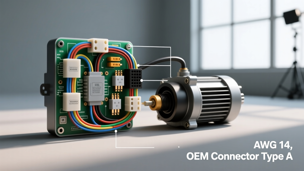
Before purchasing tools or materials, it is vital to understand the architecture of a typical 3-pin or 4-pin EWP connector. Most OEM wiring diagrams for water pumps (such as those found in VAG and BMW platforms) utilize a 3-pin TE Connectivity Superseal 1.5 or Molex MX150 connector. The circuit is divided into high-amperage power delivery and low-amperage data signaling.
| Pin | Function | Wire Color (Typical OEM) | AWG Size | Circuit Type |
|---|---|---|---|---|
| 1 | KL30 / Battery Positive | Red / White Stripe | 10 AWG | High Current (Up to 30A) |
| 2 | KL31 / Chassis Ground | Brown | 10 AWG | High Current Ground |
| 3 | PWM Signal / LIN Bus | Blue / White Stripe | 18 AWG | Low Current Data (5V-12V) |
When analyzing the wiring diagram, water pump failures are rarely caused by the internal brushless motor itself. Instead, voltage drop on the 10 AWG power feed or signal degradation on the 18 AWG PWM wire accounts for over 80% of EWP diagnostic trouble codes (DTCs) such as BMW's 20A801 (Coolant Pump, Activation).
Essential Diagnostic & Installation Tooling Costs
Diagnosing a PWM-controlled EWP requires more than a standard test light. Because the Engine Control Module (ECM) modulates the ground or signal wire at frequencies typically ranging from 100Hz to 500Hz, a standard Digital Multimeter (DMM) will only display an averaged, often misleading, voltage. To properly analyze the wiring diagram and water pump operation, the following tools represent the industry standard for cost-to-performance ratio.
1. Automotive Oscilloscope (PicoScope)
To verify the PWM duty cycle commanded by the ECU versus the actual signal reaching the pump, an oscilloscope is mandatory. A 2-channel or 4-channel PicoScope (e.g., 2204A or 4225A) allows you to capture the square wave signal. Estimated Cost: $150 (2204A) to $450 (4225A). This tool will instantly reveal if a chafed 18 AWG signal wire is causing the square wave to round off or drop voltage, which a DMM would miss entirely. For deeper insights into waveform analysis, refer to the PicoScope Automotive Diagnostics Guide.
2. High-Quality Ratcheting Crimpers
If you are repairing a pigtail or building an aftermarket harness, hand-crimping with pliers is unacceptable for high-amperage EWP circuits. You must use ratcheting crimpers designed for open-barrel or closed-barrel terminals. For TE Superseal connectors, the TE Connectivity 58459-1 or an equivalent IWISS ratcheting crimper is required to ensure a gas-tight connection that resists engine bay vibration and thermal cycling. Estimated Cost: $45 - $110.
3. Thermal Imaging Camera
A thermal imager (like the FLIR ONE Pro) is invaluable for spotting voltage drop across EWP connectors without back-pinning. A failing crimp or corroded pin on the 10 AWG power feed will generate significant heat under the 20A+ load of a water pump operating at 100% duty cycle. Estimated Cost: $200 - $300.
Material Specifications and Harness Fabrication Costs
When building a custom harness for an aftermarket EWP or repairing an OEM loom, selecting the correct wire insulation is non-negotiable. Standard PVC wire will melt or become brittle in the engine bay. You must adhere to the SAE J1128 Low Tension Primary Cable Standard, which dictates the use of cross-linked polyethylene (XLPE) insulation.
| Wire Type | Insulation Thickness | Temp Rating | Best Application | Cost per 100ft Spool |
|---|---|---|---|---|
| TXL | 0.58mm | 125°C | Tight engine bay routing, OEM replacements | $25 - $35 |
| GXL | 0.76mm | 125°C | General EWP power feeds, high abrasion areas | $28 - $40 |
| SXL | 1.02mm | 125°C | High-heat zones (near exhaust manifolds) | $35 - $50 |
For a complete aftermarket EWP150 installation using a digital controller, you will need approximately 15 feet of 10 AWG TXL (power and ground), 10 feet of 18 AWG TXL (sensor and PWM signals), a 40A automotive relay (if bypassing the internal controller), and a heavy-duty fuse block. Total material cost for a professional-grade, loom-wrapped harness is typically between $65 and $95, a fraction of the cost of a dealer-supplied OEM replacement harness which can exceed $250.
OEM vs. Aftermarket PWM Controller Cost Analysis
A major decision when referencing a wiring diagram for a water pump is whether to retain the OEM PWM logic or install an aftermarket thermal switch controller. OEM EWPs rely on the vehicle's main ECU to calculate flow rate based on coolant temp, ambient air temp, and AC pressure. If you are swapping an OEM EWP into a custom build (like an LS swap using a BMW auxiliary pump), you lose the ECU logic.
Aftermarket solutions, such as the Davies Craig Digital Controller, read an inline coolant temperature sensor and output a PWM signal to the pump. Cost Comparison:
- OEM ECU Reprogramming/Emulator: $150 - $400 (Requires specialized tuning software or standalone PWM emulator modules).
- Aftermarket Digital Controller Kit: $110 - $140 (Includes dial, temp sensor, and wiring pigtails. Reference the Davies Craig EWP Controller Installation Manual for specific wiring schematics).
- Basic Relay & Thermal Switch (On/Off): $25 - $40 (Not recommended; causes water hammer and fails to manage heat soak after engine shutdown).
Real-World Failure Modes & Voltage Drop Troubleshooting
When consulting the wiring diagram, water pump diagnostics must always include a loaded voltage drop test. A common failure mode on platforms like the Ford 3.5L EcoBoost involves the auxiliary electric water pump connector. The rubber seal in the connector degrades, allowing coolant wicking or moisture ingress. This causes micro-corrosion on the 10 AWG terminal.
The Symptom: The ECU commands 85% PWM duty cycle, but the pump only spins at 40% capacity, leading to turbocharger overheating and limp mode.
The Fix: Do not simply clear the code. Connect your DMM in DC Volts. Place the positive lead on the battery positive post and the negative lead on the pump's Pin 1 terminal (back-pinned). Run the pump via a bi-directional scan tool. A voltage drop reading greater than 0.2V on the power side, or 0.1V on the ground side, indicates high resistance. You must cut back the harness past the green corrosion, crimp on new sealed terminals using a ratcheting tool, and apply dielectric grease to the connector cavity.
By investing in the proper oscilloscopes, adhering to SAE wire standards, and understanding the financial breakdown of OEM versus aftermarket controllers, you can accurately diagnose, repair, and fabricate water pump wiring harnesses that survive the harsh realities of the modern engine bay.