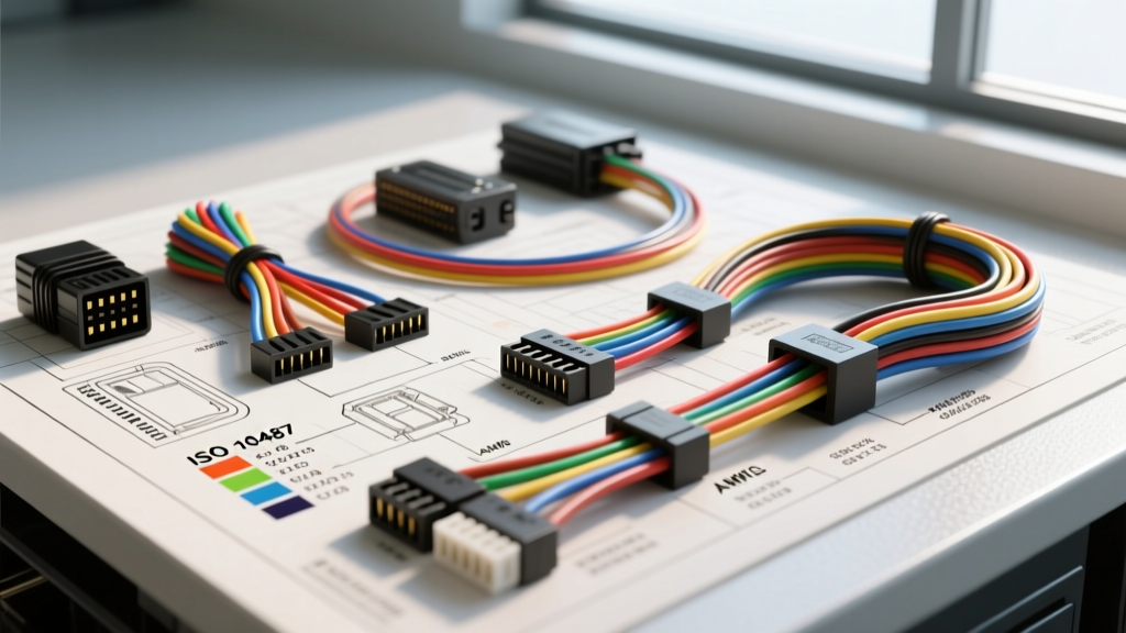
Introduction to Automotive Head Unit Schematics
Interpreting a wiring diagram for stereo system installations requires a firm understanding of both aftermarket industry standards and proprietary OEM network topologies. While older vehicles relied on simple analog 12V triggers and discrete speaker wires, modern infotainment architectures integrate the head unit into the vehicle's Controller Area Network (CAN-bus). This technical reference outlines the universal EIA/CEA color codes, ISO 10487 connector pinouts, AWG current capacities, and diagnostic procedures necessary for flawless audio integration.
EIA/CEA Standard Aftermarket Color Codes
The Consumer Technology Association (formerly CEA/EIA) established a universal color-coding standard for aftermarket car audio. When reading an aftermarket wiring diagram for stereo system harnesses, you will encounter the following discrete wire assignments. Adhering to these colors prevents catastrophic failures, such as back-feeding 12V into a low-voltage data bus.
Power, Ground, and Accessory Wires
| Wire Color | Function | Typical AWG | Voltage / Signal |
|---|---|---|---|
| Yellow | Constant 12V (Battery / Memory) | 16-18 AWG | 12.6V DC (Continuous) |
| Red | Switched 12V (Ignition / Accessory) | 16-18 AWG | 12.6V DC (Key ON) |
| Black | Chassis Ground | 16-18 AWG | 0V Reference |
| Blue | Power Antenna Trigger | 18 AWG | +12V DC (Max 300mA) |
| Blue/White | Amplifier Remote Turn-On | 18 AWG | +12V DC (Max 500mA) |
| Orange | Illumination / Dimmer | 18-20 AWG | 0-12V DC Variable |
Speaker Output Phase Wires
Speaker wires are paired, utilizing a solid color for the positive (+) phase and a solid color with a black tracer (stripe) for the negative (-) phase. Reversing phase causes destructive acoustic interference, severely degrading bass response and stereo imaging.
| Channel | Positive (+) | Negative (-) |
|---|---|---|
| Left Front (LF) | White | White/Black |
| Right Front (RF) | Gray | Gray/Black |
| Left Rear (LR) | Green | Green/Black |
| Right Rear (RR) | Purple | Purple/Black |
ISO 10487 and OEM Quadlock Connector Pinouts
For European and many global platforms, the ISO 10487 standard dictates the physical connector and pin layout for automotive radios. The standard uses two primary blocks: Block A (Power) and Block B (Speakers). However, modern VW, Audi, and BMW platforms utilize the 24-pin Quadlock (Fakra) connector, which encapsulates power, speakers, and high-speed CAN data in a single housing.
Quadlock (24-Pin) Block A Pin Configuration
- Pin 1: Permanent 12V (Terminal 30) - 16 AWG
- Pin 4: Switched 12V (Terminal 15) or CAN-Wake - 16 AWG
- Pin 5: Telephone Mute / Amp Trigger
- Pin 6: Illumination (Terminal 58s)
- Pin 8: Chassis Ground (Terminal 31) - 14 AWG (High Current)
Expert Note: On many 2005+ VAG (Volkswagen Auto Group) vehicles, Pin 4 does not provide a traditional 12V ignition signal. Instead, the radio is woken via a CAN-bus message. Installing an aftermarket head unit without a CAN-bus decoder will result in the radio failing to turn on, or worse, causing a parasitic draw that drains the battery because the unit never receives the network 'sleep' command.
Wire Gauge (AWG) and Voltage Drop Specifications
A critical aspect often omitted from basic wiring diagrams is wire gauge sizing. Automotive electrical systems operate nominally at 13.8V to 14.4V (alternator charging). Undersized power wires introduce resistance, leading to voltage drop, head unit reset issues during heavy bass transients, and potential thermal events.
| AWG Size | Max Current (Chassis Wiring) | Max Length @ 3% Drop (14.4V) | Application |
|---|---|---|---|
| 18 AWG | 6 Amps | 8 ft | Remote Turn-On, Illumination |
| 16 AWG | 10 Amps | 10 ft | Standard Head Unit Power/Ground |
| 12 AWG | 20 Amps | 12 ft | High-Power Head Units (No Amp) |
| 8 AWG | 40 Amps | 15 ft | Class D Subwoofer Amplifiers |
| 4 AWG | 100 Amps | 18 ft | Multi-Channel System Main Power |
According to CTA (Consumer Technology Association) standards, amplifier power wire must be sized based on the total RMS draw, not the peak marketing wattage. Use the formula: Total RMS Wattage / 0.6 (Efficiency) / 13.8V = Total Amperage.
Advanced Troubleshooting and Diagnostics
When the physical installation matches the wiring diagram but the system exhibits faults, systematic multimeter diagnostics are required.
Symptom: Alternator Whine in Audio Signal
Alternator whine is a high-pitched noise that modulates with engine RPM. It is caused by a ground loop, where the head unit and the amplifier are grounded at different chassis points with varying resistance, allowing AC ripple from the alternator to enter the RCA shield.
- Verify Ground Integrity: Set your Digital Multimeter (DMM) to DC Voltage. Measure between the head unit RCA outer shield and the amplifier RCA input shell. A reading above 0.05V indicates a ground potential difference.
- Check AC Ripple: Set the DMM to AC Voltage. Measure the vehicle battery with the engine running. If AC voltage exceeds 50mV (0.05V AC), the vehicle's alternator diode bridge is failing, injecting noise into the entire DC system.
- Isolate the Signal: Use a ground loop isolator on the RCA lines only as a last resort, as they can attenuate high-frequency audio response. The correct fix is to star-ground all audio components to a single, bare-metal chassis point using 8 AWG or thicker wire.
Symptom: Head Unit Resets on Heavy Bass Hits
This is a classic voltage drop issue. The internal amplifier of the head unit demands high transient current. If the 16 AWG power wire or the factory fuse tap is undersized, voltage at the radio's Yellow wire drops below 9V, triggering the unit's internal undervoltage protection reset.
- Diagnostic Step: Connect a DMM directly to the Yellow and Black wires at the back of the radio harness. Play a 40Hz sine wave test tone at 80% volume.
- Specification: If the voltage dips below 11.5V, you must upgrade the power delivery. Run a dedicated 12 AWG or 10 AWG wire directly from the battery or a high-amperage distribution block, bypassing the factory dash harness.
CAN-Bus and Data Line Integration
Modern vehicles (2010+) utilize multiplexed data networks. In GM vehicles (GMLAN), Ford (MS-CAN/HS-CAN), and Chrysler (CAN-IHS), the steering wheel controls, door chimes, and accessory power states are broadcast over twisted-pair data lines (typically CAN-H and CAN-L). A standard wiring diagram for stereo system replacements in these vehicles will show a data bus interface module splicing into the OBD-II diagnostic port or the radio harness data pins.
Twisted Pair Specs: CAN-H and CAN-L must remain twisted at a rate of 1 twist per inch to maintain the 120-ohm impedance and reject electromagnetic interference (EMI). Never untwist more than 2 inches of the data pair when soldering to an interface harness. For deeper automotive network diagnostics, refer to SAE J1939 and related CAN standards for termination resistance and topology rules. A healthy CAN network with two 120-ohm terminating resistors will read exactly 60 ohms when measured across CAN-H and CAN-L with an ohmmeter.
Parasitic Draw Testing Protocol
Aftermarket CAN-bus interfaces can sometimes fail to enter sleep mode, draining the vehicle battery overnight. To verify proper integration:
- Set the DMM to the 10A Amperage setting and connect it in series between the negative battery terminal and the negative cable.
- Close all doors, lock the vehicle, and wait for the BCM to enter sleep mode (typically 15 to 25 minutes on modern architectures).
- Acceptable Draw: Less than 50mA (0.05A).
- Fault Condition: If the draw remains above 300mA, the stereo interface module is keeping the data bus awake. You must re-flash the interface firmware or reconfigure the DIP switches to match the exact vehicle year and trim level.
Conclusion
Mastering the wiring diagram for stereo system integration goes far beyond matching red to red and black to black. It requires a comprehensive grasp of AWG current limits, ISO/Quadlock pinouts, CAN-bus wake signals, and rigorous ground-loop diagnostics. By treating the head unit as a critical node in the vehicle's broader electrical architecture, installers can achieve OEM-level reliability and pristine audio fidelity without compromising vehicle network stability.