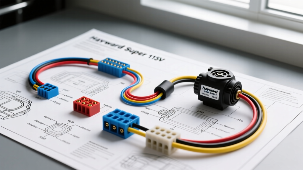
Integrating High-Flow Auxiliary Pumps in Mobile Platforms
When engineering high-capacity auxiliary fluid transfer or custom liquid cooling systems for heavy-duty RVs, marine vessels, or off-grid automotive dyno environments, selecting the right circulation hardware is only half the battle. The electrical integration of these systems requires a deep understanding of AC induction motors, inductive surge loads, and mobile power distribution. For custom automotive and marine builders, the Hayward Super Pump wiring diagram 115V configuration serves as a critical reference point. Originally designed for high-volume residential and commercial fluid circulation, the Hayward Super Pump (frequently equipped with A.O. Smith or Century dual-voltage motors) is frequently repurposed in mobile platforms for large-scale heat exchange, custom marine bilge/cooling loops, and RV shore-power water features.
Wiring a 115V AC inductive motor in a high-vibration, mobile environment introduces unique challenges. Unlike standard 12V DC automotive water pumps, a 115V AC motor requires precise terminal block configuration, pure sine wave inverter compatibility, and strict adherence to marine and RV grounding standards. This complete wiring walkthrough details the exact terminal pinouts, AWG wire sizing, and troubleshooting protocols required to safely integrate a 115V Hayward Super Pump into your mobile or off-grid electrical system.
Decoding the Dual-Voltage Motor Terminal Block
Most Hayward Super Pump models utilize a dual-voltage (115V/230V) single-phase AC induction motor. The motor's terminal block contains a series of numbered pins (typically 1 through 4) and a ground screw. The voltage is selected by physically moving the internal jumper wires or rotating a voltage selector switch on the terminal board. For a 115V setup, the motor windings are configured in parallel to handle the higher amperage draw associated with lower voltage.
In a 115V configuration, the motor will draw approximately 14.5 to 16.0 amps under a full 1 HP or 1.5 HP load, with a Locked Rotor Amperage (LRA) surge that can briefly exceed 45 amps during startup. Understanding the exact terminal layout is crucial to prevent shorting the start and run windings.
Terminal Block Pinout and Wire Color Codes (115V Setup)
| Terminal / Pin | Function | Standard Wire Color | AWG / Spec |
|---|---|---|---|
| L1 (Line) | 115V AC Hot Feed | Black | 10 AWG Stranded (Marine) |
| L2 (Neutral) | 115V AC Neutral Return | White | 10 AWG Stranded (Marine) |
| Ground (Chassis) | Equipment Grounding | Green or Green/Yellow | 10 AWG Stranded |
| Bonding Lug | Equipotential Bonding | Bare Solid Copper | 8 AWG Solid Copper |
Note: Always verify the internal jumper setting on the motor's terminal board. If the motor is shipped with a 230V default configuration, applying 115V to the L1 and L2 terminals without adjusting the parallel jumpers will result in the motor running at half-speed, overheating, and eventually tripping the internal thermal overload protector.
Inverter Sizing and AWG Wire Selection
In automotive, RV, and marine applications, 115V power is rarely sourced directly from a utility grid. It is typically generated by a DC-to-AC inverter connected to a 12V, 24V, or 48V lithium or AGM battery bank. Because AC motors are highly inductive loads, they require a massive surge of current to establish the magnetic field in the start winding before the centrifugal switch disengages.
Running a Hayward Super Pump on a Modified Sine Wave (MSW) inverter is strongly discouraged. The harmonic distortion of an MSW will cause the motor to run hotter, produce an audible hum, and degrade the insulation on the copper windings prematurely. A Pure Sine Wave (PSW) inverter is mandatory for this application.
Wire Gauge and Breaker Sizing Chart
| Motor HP | Running Amps (115V) | Surge / LRA | Recommended Inverter Size | Min. Circuit AWG (Marine) | AC Breaker Size |
|---|---|---|---|---|---|
| 1.0 HP | 13.8 A | ~42 A | 2000W Pure Sine Wave | 12 AWG (up to 15ft) | 20 Amp |
| 1.5 HP | 16.0 A | ~48 A | 3000W Pure Sine Wave | 10 AWG (up to 20ft) | 25 Amp |
According to the American Boat & Yacht Council (ABYC) E-11 AC Standards, all branch circuit wiring in marine environments must utilize stranded, tinned copper wire (UL 1426) to resist corrosion and vibration-induced fatigue. Standard solid-core THHN wire used in residential automotive dyno setups is prone to snapping under vehicular vibration and should be avoided in mobile platforms.
Grounding vs. Equipotential Bonding
A frequent point of failure in mobile pump installations is the confusion between equipment grounding and equipotential bonding. The NFPA 70 National Electrical Code (NEC) and ABYC standards draw a strict line between these two safety mechanisms.
- Equipment Grounding (Green Wire): This is the safety path that carries fault current back to the inverter's AC breaker panel to trip the breaker in the event of a short circuit. This wire connects to the motor's internal ground screw and the external chassis ground lug.
- Equipotential Bonding (Bare 8 AWG Solid): If the pump is handling fluid that contacts the user (e.g., an RV outdoor shower system or marine deck wash), a continuous bare 8 AWG solid copper bonding wire must be attached to the pump's external bonding lug and tied to the vehicle's main grounding bus bar. This prevents voltage gradients between the fluid, the pump housing, and the vehicle chassis.
Step-by-Step 115V Wiring Walkthrough
Follow this precise sequence to wire the Hayward Super Pump to your mobile 115V distribution panel:
- Disconnect All Power: Shut off the main DC battery disconnect and ensure the inverter is powered down. Verify zero voltage at the AC breaker panel using a digital multimeter.
- Verify Motor Voltage Setting: Remove the motor's rear electrical cover. Locate the terminal board and ensure the jumper wires are set to the 115V parallel configuration as indicated by the schematic printed on the inside of the cover plate.
- Prepare the Conduit and Wire: Route liquid-tight flexible non-metallic conduit (LFNC) from your AC junction box to the motor. Pull three conductors of 10 AWG marine-grade stranded wire (Black, White, Green).
- Terminate the Ground: Crimp a ring terminal onto the Green wire. Attach it to the motor's external grounding screw. Torque to 12 in-lbs to ensure vibration resistance.
- Connect Line and Neutral: Strip 3/8" of insulation from the Black (L1) and White (L2) wires. Insert them into the corresponding quick-connect terminals or screw terminals on the motor board. Note: On single-phase 115V AC circuits, line and neutral polarity does not affect motor rotation, but maintaining standard color-coding is critical for downstream troubleshooting.
- Attach the Bonding Wire: If required by your specific mobile application, attach an 8 AWG solid bare copper wire to the external brass bonding lug on the pump housing.
- Secure and Seal: Replace the terminal cover, ensuring the rubber O-ring gasket is seated properly to prevent moisture ingress. Apply a bead of marine-grade silicone sealant around the conduit fitting.
- Test the Circuit: Re-energize the DC bank, turn on the inverter, and flip the 20A/25A AC breaker. The motor should start within 0.5 seconds with a brief hum, transitioning to a smooth operational tone.
Troubleshooting: Capacitor and Centrifugal Switch Failures
Even with perfect wiring, 115V AC induction motors are subject to mechanical and electrical wear. When diagnosing a Hayward Super Pump in an automotive or RV setting, use the following decision tree:
Symptom: Motor Hums but Fails to Rotate
This indicates that the run winding is receiving power, but the start winding is not engaging. The centrifugal switch may be stuck, or the start capacitor has failed.
- Test the Capacitor: Disconnect power, discharge the capacitor using a 20,000-ohm resistor, and remove it. Set your multimeter to the Microfarad (µF) setting. A typical 1 HP motor uses a 124-149 µF start capacitor. If the reading is below 100 µF or shows an open circuit (OL), replace the capacitor.
- Inspect the Centrifugal Switch: Remove the rear bell housing. Check the copper contacts on the centrifugal governor for carbon buildup or pitting. Clean with fine-grit emery cloth.
Symptom: Inverter Overload / Breaker Trips on Startup
If the AC breaker trips instantly or the inverter faults, the inductive surge is exceeding the system's capacity, or there is a hard short.
- Check for Impeller Binding: Disconnect power and manually rotate the motor shaft via the rear slotted screwdriver access point. If the shaft is stiff, the impeller may be jammed with debris, causing the LRA to sustain indefinitely and trip the breaker.
- Measure Voltage Drop: Measure the AC voltage at the inverter output and then at the motor terminals while the motor attempts to start. If the voltage at the motor drops below 105V, your wire run is too long or the AWG is too small, causing excessive voltage drop and amperage spike.
For comprehensive technical specifications and OEM replacement parts, refer to Hayward Industries Technical Documentation. Proper adherence to these wiring protocols ensures that your high-flow auxiliary pump operates safely and reliably, whether it is cooling a custom automotive engine block on a dyno or circulating water in a luxury marine vessel.