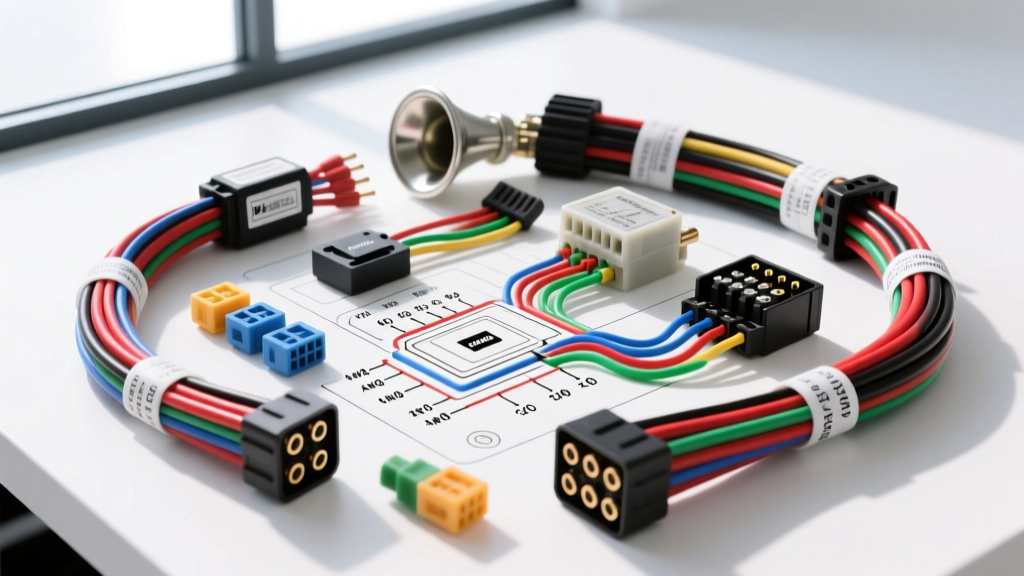
Introduction to High-Current Acoustic Circuits
Upgrading to a set of Hella Supertone or Sharptone air horns is one of the most effective safety modifications you can perform on a daily driver or off-road vehicle. Producing up to 118 dB of acoustic output, these dual-tone electromechanical horns require a massive, instantaneous surge of electrical current to drive their internal tungsten diaphragms. However, the factory horn circuit in 95% of modern vehicles is entirely inadequate for this task. OEM horn wiring is typically designed for a single, low-current 3A to 5A disc horn, utilizing thin 18 AWG or 20 AWG wiring routed through the Body Control Module (BCM) or a low-amperage steering wheel clock spring.
If you attempt to wire Hella horns directly to the OEM horn trigger, you risk melting the clock spring ribbon cable, frying the BCM's internal solid-state relay, or causing a severe voltage drop that results in a weak, stuttering horn sound. To achieve the full acoustic potential of the Hella Supertone kit, you must construct a dedicated high-current secondary circuit using an ISO-standard automotive relay. This advanced technical deep dive will walk you through the exact Hella horn wiring diagram, wire gauge mathematics, and modern OEM integration protocols required for a flawless, fire-safe installation.
Hella Supertone & Sharptone Electrical Specifications
Before designing the circuit, we must establish the baseline electrical load. Hella's dual-tone horns operate on a standard 12V nominal system but experience significant inrush current when the electromagnetic coil is first energized and the diaphragm is at rest. According to Hella Technical Installation Guidelines, the combined steady-state draw of a High/Low frequency Supertone pair is approximately 18 to 22 Amps, with peak inrush spikes potentially exceeding 30 Amps for the first 50 milliseconds.
| Horn Model | Frequency (Hz) | Nominal Current | Peak Inrush | Min. Power Wire (AWG) | Min. Ground Wire (AWG) |
|---|---|---|---|---|---|
| Supertone (High) | 500 Hz | 9A - 11A | 15A | 14 AWG | 14 AWG |
| Supertone (Low) | 300 Hz | 9A - 11A | 15A | 14 AWG | 14 AWG |
| Combined Circuit | Dual Tone | 18A - 22A | 30A | 12 AWG (10 AWG pref) | 12 AWG |
For the main power feed from the battery to the relay, and from the relay to the horn split, you must use a minimum of 12 AWG wire. For professional builds, we highly recommend 10 AWG TXL (Thin-wall Cross-linked) wire, which complies with the SAE J1128 Low Tension Primary Cable Standard. TXL wire offers superior heat resistance and voltage retention compared to standard PVC primary wire, which is critical in high-temperature under-hood environments.
The Core Hella Horn Wiring Diagram: Relay Integration
The heart of the Hella horn wiring diagram is the standard 4-pin Bosch-style ISO relay. This electromechanical switch allows a low-current OEM trigger signal (typically 1A to 5A) to safely control the high-current 20A+ load required by the aftermarket horns. Below is the exact pinout matrix and routing protocol for the secondary circuit.
ISO 4-Pin Relay Pinout Matrix
| Relay Pin | Internal Function | Wire Color (Standard) | Routing Destination & Specification |
|---|---|---|---|
| 30 | Common (Input Power) | Red (10 AWG) | Direct to Battery Positive (+) via an inline 30A MAXI fuse, located within 18 inches of the battery terminal. |
| 85 | Coil Ground | Black (16 AWG) | Direct to a clean, bare-metal chassis ground point. Do not share this ground with high-draw accessories. |
| 86 | Coil Trigger (+12V) | Yellow (16 AWG) | Spliced into the OEM positive horn trigger wire. (See BCM/Multiplexing warning below). |
| 87 | Normally Open (Output) | Red (12 AWG) | Routed to a weather-sealed splitter, then branching into two 14 AWG leads to the positive terminals of the High and Low Hella horns. |
Grounding the Horns: The Acoustic Resonance Factor
Electromechanical horns are incredibly sensitive to voltage fluctuations. If the ground path has high resistance, the voltage at the horn coil will drop below the 11.5V threshold required to fully magnetize the core. This results in the diaphragm oscillating at the wrong frequency, producing a weak, rattling, or single-tone sound. Never rely on the horn mounting bracket for the primary ground. You must run a dedicated 12 AWG ground wire from the negative terminal of each Hella horn directly to a verified, sanded chassis ground point, terminating with a heat-shrink-sealed ring terminal coated in dielectric grease.
Advanced OEM Integration: Navigating Modern BCMs and LIN Bus
The most complex aspect of executing the Hella horn wiring diagram on a late-model vehicle (2015 and newer) is tapping the OEM trigger signal without destroying the vehicle's Body Control Module (BCM). In older vehicles, pressing the horn button on the steering wheel physically completed a 12V circuit. In modern architectures, the steering wheel button sends a digital message via a LIN (Local Interconnect Network) bus or a multiplexed CAN signal to the BCM, which then activates a low-side solid-state driver to ground the OEM horn.
How to Safely Probe and Tap the Trigger
- Locate the OEM Horn Connector: Find the factory horn near the radiator core support and disconnect the 2-pin weather-pack connector.
- DMM Voltage Test: Set your Digital Multimeter to DC Volts. Back-probe the two wires at the harness side with the ignition ON and the horn button pressed.
- Scenario A (Traditional): One wire shows 0V, the other jumps to +12V. This is a standard positive trigger. You can safely splice Pin 86 of your relay to the +12V wire.
- Scenario B (Low-Side Switched): One wire shows constant +12V, the other shows 0V but drops to near 0V (or completes to ground) when the button is pressed. Stop. If you wire a relay coil to a low-side BCM driver, the inductive kickback from the relay coil collapsing can fry the BCM's internal transistor.
- Scenario C (LIN Bus/Multiplexed): Both wires show varying low voltage (e.g., 7V to 10V) or PWM signals. This is a data bus. Tapping into this will cause network faults and check engine lights.
- The Isolation Solution: If you encounter Scenario B or C, you must use an isolation diode (1N4007) across the relay coil (Pins 85 and 86, stripe facing 86) to suppress inductive flyback. For LIN bus systems, you must use a dedicated CAN-bus horn decoder module that reads the digital network traffic and provides a clean, isolated 12V trigger for your relay's Pin 86.
Advanced Troubleshooting & Voltage Drop Testing
If your Hella horns are installed but sound weak, stutter, or only produce one tone, do not immediately assume the horns are defective. The issue is almost certainly a voltage drop in your wiring. According to SAE standards, a high-current circuit should not experience more than a 0.5V drop across the entire power and ground path under load.
The Voltage Drop Testing Protocol
To perform this test, you need a helper to press the horn button inside the cabin while you monitor the DMM outside.
- Test the Power Side: Set the DMM to DC Volts. Place the red probe on the Battery Positive (+) terminal and the black probe on the Hella Horn Positive (+) terminal. Press the horn. A reading above 0.3V indicates excessive resistance in the power wire, the fuse holder, or the relay contacts (Pin 30 to 87).
- Test the Ground Side: Place the red probe on the Hella Horn Negative (-) terminal and the black probe on the Battery Negative (-) terminal. Press the horn. A reading above 0.2V indicates a poor chassis ground, undersized ground wire, or corroded ring terminal.
- Test the Trigger Circuit: Place the red probe on the Battery Positive (+) and the black probe on Relay Pin 86. Press the horn. If you see a massive voltage drop here, your OEM trigger wire is undersized or the clock spring is failing under the 0.2A load of the relay coil.
Common Failure Modes in Aftermarket Horn Circuits
- Non-Ratcheting Crimps: Using pliers to crush terminals instead of a ratcheting crimper creates micro-voids inside the barrel. Under the 20A load of the Hella horns, these voids generate immense heat, melting the insulation and causing intermittent failures.
- Undersized Fusing: Using a 15A fuse for a combined 22A circuit will result in the fuse blowing instantly upon the inrush spike. Always use a 30A ATO or MAXI fuse for dual Supertone setups.
- Moisture Intrusion: The Hella Supertone horns feature a drainage slot on the bottom of the bell. If mounted facing upward or horizontally without drip loops in the wiring, water will wick into the electromagnetic coil via capillary action, causing an internal short. Always mount the bells facing downward at a minimum 15-degree angle.
Summary of Best Practices
Executing a flawless Hella horn wiring diagram requires respecting the physics of high-current acoustic circuits. By utilizing 10 AWG TXL wire for the main feeds, implementing a properly fused Bosch-style ISO relay, suppressing inductive flyback to protect modern BCMs, and verifying the circuit with strict voltage drop testing, you will achieve a reliable, ear-splitting 118 dB warning system that will outlast the vehicle itself. Always prioritize heat-shrink-sealed, adhesive-lined ring terminals and dielectric grease on every under-hood connection to combat galvanic corrosion and ensure long-term electrical conductivity.