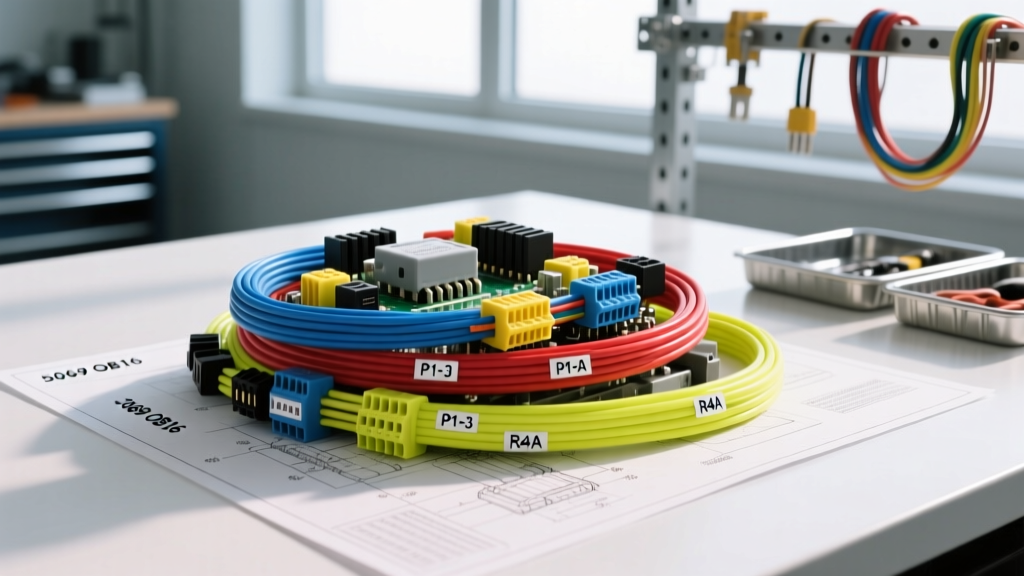
Introduction to Multiplexed Chassis Control in Heavy-Duty Vehicles
Custom expedition vehicles, heavy-duty commercial trucks, and advanced EV conversions are increasingly moving away from traditional, heavy copper fuse boxes in favor of multiplexed Programmable Logic Controller (PLC) systems. At the heart of many high-end 24V DC vehicle builds is the Allen-Bradley 5069-OB16, a Compact 5000 I/O 16-point 24V DC source output module. While originally designed for industrial automation, the 5069-OB16 is exceptionally well-suited for automotive applications where programmable logic is required to manage Power Take-Off (PTO) engagement, differential lockers, lighting contactors, and pneumatic solenoids.
Understanding the 5069 OB16 wiring diagram is critical for automotive electrical engineers and custom fabricators. Unlike standard OEM automotive ECUs that utilize low-side (sink) drivers, the 5069-OB16 acts as a high-side (source) switch. This means the module provides the +24V potential to the load, and the load is completed by grounding to the vehicle chassis or a dedicated common bus. This comprehensive walkthrough details the Removable Terminal Block (RTB) pinout, relay integration, inductive load suppression, and heavy-duty wiring standards required to deploy this module in harsh vehicular environments.
5069 OB16 Wiring Diagram: RTB Pinout and Terminal Layout
The 5069-OB16 utilizes a 36-pin Removable Terminal Block (RTB). Proper termination of this block is the first step in ensuring a reliable vehicle harness. Because automotive environments are subject to severe vibration (SAE J2202 standards), all stranded TXL or GXL cross-linked automotive wires must be terminated with insulated bootlace ferrules before insertion into the RTB. Open-barrel crimps or bare stranded wire will fray, cause short circuits, and fail under chassis vibration.
Power and Ground Distribution (VDC and COM)
The module requires a stable 24V DC supply. In a vehicle, the 24V system can experience severe transients, including alternator load dumps that can spike system voltage well beyond 30V. Therefore, the VDC input should never be wired directly to a raw battery bus without transient protection.
- Terminals 16, 17, 18, 19 (VDC): Connect to the +24V DC power supply. Use 14 AWG GXL red wire, protected by an automotive-grade TVS (Transient Voltage Suppressor) diode and an isolated DC-DC converter to ensure clean, regulated 24V power.
- Terminals 20, 21, 22, 23 (COM): Connect to the vehicle's 0V ground reference. Use 14 AWG GXL black wire. Do not rely on chassis grounding for the module's COM; run a dedicated ground wire back to the main vehicle negative bus bar to prevent ground loops and logic faults.
16-Point Output Channel Mapping
The output channels are mapped sequentially across the RTB. As a source output module, current flows from the internal VDC bus, through the solid-state switch, and out to the load.
- Terminals 00 through 15: Output channels 0 to 15. Each channel is rated for a maximum continuous current of 0.5A per point (with a group maximum that requires careful load calculation). These terminals will connect to the control coils of automotive relays or low-current indicator solenoids.
- Terminals 24 through 35: Shield and spare terminals. In high-noise automotive environments (e.g., near EV traction inverters or heavy-duty alternators), route your harness shield drain wires to these designated shield terminals to prevent EMI from inducing false logic triggers.
Integrating 24V DC Source Outputs with Automotive Relays
Because the 5069-OB16 outputs are limited to 0.5A per channel, they cannot directly drive high-current automotive loads like starter solenoids, air compressors, or winch contactors. Instead, the module is used to trigger the coils of heavy-duty automotive relays, such as the ubiquitous 5-pin Bosch ISO mini relay or heavy-duty Gigavac contactors.
Standard 5-Pin Bosch Relay Integration
When wiring a standard 24V automotive relay to the 5069-OB16 source output, the circuit is completed as follows:
- Pin 86 (Coil Input): Connect to the assigned 5069-OB16 output terminal (e.g., Terminal 04) using 18 AWG wire.
- Pin 85 (Coil Ground): Connect to the vehicle's local ground bus or chassis ground point using 18 AWG wire.
- Pin 30 (Common / High Current Feed): Connect to the fused +24V heavy-duty battery feed (typically 10 AWG or 12 AWG depending on the load).
- Pin 87 (Normally Open Output): Connect to the positive terminal of the automotive load (e.g., PTO solenoid, lighting contactor).
- Pin 87a (Normally Closed): Left unconnected and insulated with heat shrink for standard NO switching applications.
When the PLC logic commands Output 04 HIGH, the 5069-OB16 sources +24V to Pin 86. Current flows through the relay coil to Pin 85 (Ground), energizing the electromagnet and pulling the high-current contactor closed.
Flyback Diode Protection for Vehicle Solenoids
Automotive relay coils and pneumatic solenoids are highly inductive loads. When the 5069-OB16 internal switch opens, the collapsing magnetic field generates a massive reverse voltage spike (inductive kickback) that can exceed 100V. While the 5069-OB16 features internal short-circuit and thermal protection, repeated exposure to inductive spikes will degrade the solid-state output transistors, leading to premature module failure.
The Fix: Always install a flyback diode across the relay coil. Wire a 1N4007 or an automotive-grade bidirectional TVS diode in parallel with the relay coil. The cathode (stripe) must face the +24V source (Pin 86 / OB16 Output), and the anode must face the ground (Pin 85). This provides a safe recirculation path for the inductive spike, protecting the PLC module.
Wire Gauge, Routing, and Harness Specifications
Adhering to SAE J2202 Heavy Duty Wiring Systems standards is non-negotiable for custom vehicle builds utilizing industrial PLCs. The table below outlines the exact specifications for the 5069-OB16 RTB pigtail harness.
| RTB Terminal | Function | SAE Wire Color | Wire Gauge (AWG) | Insulation Type | Destination / Note |
|---|---|---|---|---|---|
| 16-19 | VDC (+24V) | Red | 14 AWG | GXL / TXL | Isolated DC-DC 24V Supply |
| 20-23 | COM (0V) | Black | 14 AWG | GXL / TXL | Main Vehicle Negative Bus |
| 00-15 | Outputs 0-15 | Yellow / Tracer | 18 AWG | GXL / TXL | Relay Coils (Pin 86) |
| 24-35 | Shield / Drain | Bare / Shield | N/A | Foil / Braid | Harness Shield Drain Wire |
Routing Best Practices: The 5069-OB16 control harness must be routed at least 12 inches away from high-voltage EV traction cables, alternator output cables, and ignition coil wires. Where crossing is unavoidable, cross the harnesses at a strict 90-degree angle to minimize electromagnetic interference (EMI). Secure the loom every 6 inches using UV-resistant zip ties and adhesive-backed mounts to prevent chafing against the vehicle chassis.
Troubleshooting Common Vehicle Integration Faults
Integrating industrial I/O into a dynamic automotive electrical system introduces unique failure modes. Below is a diagnostic decision tree for common issues encountered when commissioning the 5069 OB16 wiring diagram in a vehicle.
Symptom: Output LED is ON, but Relay Does Not Click
- Cause 1: High-Resistance Ground. The vehicle chassis ground at the relay coil (Pin 85) has paint, rust, or corrosion, preventing the circuit from completing. Fix: Scrape the chassis to bare metal, apply dielectric grease, and use a star washer for the ground ring terminal.
- Cause 2: Voltage Drop on VDC Input. If the wire gauge supplying Terminals 16-19 is too small, the module may not have enough potential to drive the relay coil. Fix: Measure voltage directly at the RTB VDC terminal while the output is active. It must read >22V.
Symptom: Module Faults Out or Blows Internal Protection on Power-Up
- Cause: Alternator Load Dump. In heavy trucks, if a battery disconnect switch is thrown while the alternator is charging, a massive voltage spike (up to 60V) can travel through the VDC input, destroying the module's internal regulation. Fix: Install an ISO 7637-2 compliant transient voltage suppressor and ensure the module is powered via an isolated, regulated DC-DC converter rather than raw battery power.
Symptom: False Triggering of Outputs (Ghost Switching)
- Cause: Capacitive Coupling / EMI. Long wire runs to relay coils acting as antennas, picking up noise from vehicle inverters or CAN bus lines. Fix: Use shielded twisted-pair (STP) cable for the output harness, terminate the shield at the RTB shield pins (24-35), and ensure the shield is grounded at the module end only to prevent ground loops.
Conclusion and Best Practices
Successfully deploying the 5069 OB16 wiring diagram in a custom vehicle build bridges the gap between industrial automation reliability and automotive ruggedness. By treating the module as a high-side source driver, properly sizing your GXL wiring with ferrule terminations, and rigorously protecting against inductive kickback and alternator load dumps, you can create a multiplexed chassis control system that is vastly superior to traditional fuse panels. For further reference on automotive relay specifications and coil suppression, consult the Bosch Automotive Mobility Datasheets and the official Rockwell Automation Compact 5000 I/O Installation Manuals. Always bench-test your RTB harness and relay logic before integrating it into the final vehicle chassis to ensure flawless operation in the field.