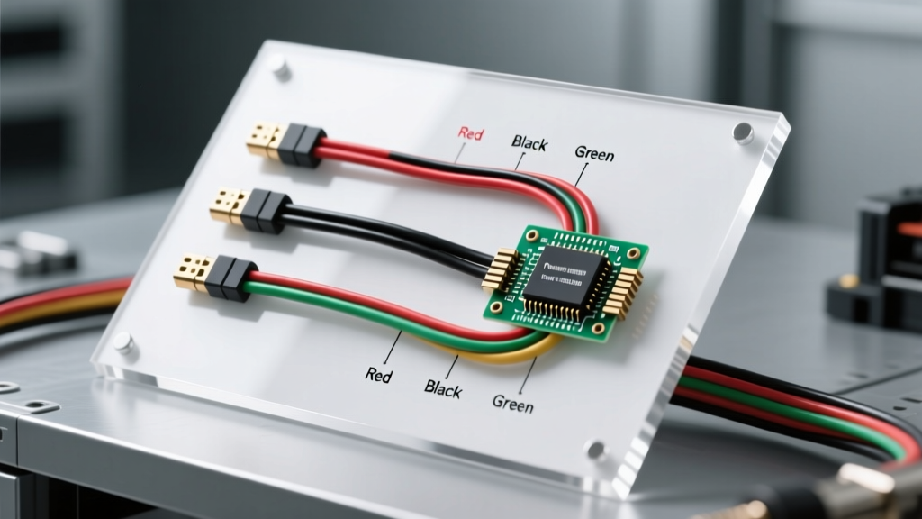
Introduction to High-Pressure Fuel Rail Sensing
Modern Gasoline Direct Injection (GDI) and High-Pressure Common Rail (HPCR) diesel engines demand extreme precision in fuel delivery. At the heart of this system is the Fuel Rail Pressure (FRP) sensor, a critical component that monitors hydraulic pressure inside the fuel rail and feeds this data to the Powertrain Control Module (PCM). Understanding the 3 wire fuel pressure sensor wiring diagram is essential for diagnosing drivability issues, hard-start conditions, and limp-mode failures associated with codes like P0190, P0191, and P0193.
Unlike older manifold absolute pressure (MAP) sensors that measure vacuum in inches of mercury (Hg), the FRP sensor measures extreme hydraulic pressure, often exceeding 3,500 PSI (240 Bar) in modern GDI applications and up to 30,000 PSI in heavy-duty diesel systems. According to Bosch Mobility Solutions GDI overview, maintaining precise rail pressure is mandatory for proper fuel atomization, emissions compliance, and preventing cylinder wash-down. This advanced technical deep dive will dissect the circuit topology, OEM wire color codes, signal mapping, and oscilloscope diagnostic strategies for 3-wire FRP sensors.
Anatomy of the 3 Wire Fuel Pressure Sensor Circuit
The standard 3-wire FRP sensor utilizes a piezoresistive strain gauge bridge. When hydraulic pressure deforms the internal diaphragm, the resistance of the bridge changes. The PCM supplies a precise voltage to the bridge, and the sensor outputs a ratiometric analog signal. The three wires are strictly defined as follows:
- 5-Volt Reference (VREF): Provides a stabilized 5.0V DC power supply from the PCM. This circuit is often shared with other critical sensors (like the APP or MAP sensor) on a common 5V bus.
- Signal Return: Carries the ratiometric analog voltage back to the PCM's Analog-to-Digital (A/D) converter. This voltage scales linearly with fuel pressure.
- Low Reference (Sensor Ground): A dedicated ground path back to the PCM. This is not a chassis ground. It is a low-side driver ground inside the PCM to prevent ground loop noise from corrupting the sensitive analog signal.
Wire Gauge and Routing Specifications
Because the FRP sensor is typically mounted directly on the high-pressure fuel rail, the wiring harness is exposed to severe under-hood temperatures and high-frequency mechanical vibration. OEMs typically use 20 AWG to 22 AWG cross-linked polyethylene (XLPE) or Tefzel-insulated copper wire for these circuits to handle the thermal load while maintaining flexibility. In high-EMI environments (such as near the ignition coils or high-pressure fuel pump solenoid), the signal wire may be routed as a twisted pair with the low reference wire or wrapped in a braided copper shield that is grounded at the PCM connector only.
Standard PCM Pinout & Wire Color Matrix
While wire colors vary by manufacturer and model year, the circuit architecture remains consistent. Below is a reference matrix for common domestic applications, including GM's Ecotec/LTG direct injection platforms and Ford's EcoBoost lineup. Always verify with a vehicle-specific service manual or Motorcraft OEM sensor specifications before piercing wires.
| Vehicle Application | Wire Function | OEM Wire Color (Typical) | PCM Pin / Connector |
|---|---|---|---|
| GM 2.0L LTG (GDI) | 5V VREF | Dark Blue | X1 / Pin 42 |
| GM 2.0L LTG (GDI) | Signal Return | Brown/White Tracer | X1 / Pin 43 |
| GM 2.0L LTG (GDI) | Low Reference | Black/White Tracer | X1 / Pin 44 |
| Ford 3.5L EcoBoost | 5V VREF | Brown/White Tracer | PCM C1381B / Pin 38 |
| Ford 3.5L EcoBoost | Signal Return | Grey/Red Tracer | PCM C1381B / Pin 39 |
| Ford 3.5L EcoBoost | Low Reference | Grey/Black Tracer | PCM C1381B / Pin 40 |
Signal Voltage vs. Pressure Mapping
The FRP sensor outputs a ratiometric signal, meaning the output voltage is directly proportional to the input supply voltage (VREF) and the measured pressure. If the PCM's 5V reference drops to 4.8V due to a parasitic draw on the shared bus, the signal output will scale down proportionally, potentially causing the PCM to miscalculate fuel pressure and trigger a P0191 (Fuel Pressure Sensor Range/Performance) code.
| Measured Signal Voltage | Approximate Fuel Pressure (GDI) | System State / Engine Mode |
|---|---|---|
| 0.50V | 0 PSI (0 Bar) | Key On, Engine Off (Residual pressure bled off) |
| 1.25V | ~750 PSI (51 Bar) | Low-Pressure Mode / Limp Home / Idle |
| 2.50V | ~2,100 PSI (145 Bar) | Normal Cruising / Partial Load |
| 3.80V | ~3,200 PSI (220 Bar) | Heavy Acceleration / High Load |
| 4.80V | ~3,500+ PSI (240+ Bar) | Wide Open Throttle (WOT) / Max Rail Pressure |
Advanced Diagnostic Troubleshooting
Diagnosing a 3-wire FRP circuit requires moving beyond simple code scanning. Because the sensor is subjected to extreme hydraulic pulsations from the High-Pressure Fuel Pump (HPFP), mechanical noise can easily bleed into the electrical signal if the harness is compromised. Furthermore, SAE J1939 standards for heavy-duty networks emphasize the necessity of clean analog grounds for high-pressure telemetry.
1. The 5V Reference Bus Load Test
A common failure mode is a skewed VREF circuit. The PCM supplies the 5V reference to multiple sensors in parallel. If a wiring chafe occurs in the MAP sensor harness, it can drag the entire 5V bus down to 4.6V. The FRP sensor will accurately report pressure based on 4.6V, but the PCM's internal logic expects a 5.0V baseline, resulting in a rationality fault.
- Step 1: Disconnect the FRP sensor and all other sensors on the shared 5V bus.
- Step 2: Backprobe the VREF wire at the PCM connector.
- Step 3: Measure voltage with a high-impedance DMM. It must read exactly 5.0V (±0.1V).
- Step 4: Reconnect sensors one by one. If the voltage drops below 4.95V upon connecting a specific sensor, that sensor or its pigtail has an internal short to ground.
2. Low Reference Voltage Drop Test
Never test the FRP ground by checking continuity to the battery negative post. The PCM uses a dedicated low-reference circuit. A poor connection inside the PCM harness connector will cause a voltage drop, artificially elevating the signal return voltage and causing the PCM to read higher fuel pressure than actually exists.
- Setup: Set DMM to DC Volts. Place the red lead on the sensor ground wire (backprobed at the sensor connector) and the black lead on the battery negative terminal.
- Condition: Engine running, HPFP active.
- Specification: The voltage drop must be strictly less than 0.05V. Any reading above 0.10V indicates terminal fretting corrosion or a broken strand in the 22 AWG ground wire.
3. Oscilloscope Waveform Analysis
Using a PicoScope or equivalent automotive oscilloscope is the only way to visualize high-frequency hydraulic noise and electrical interference. Connect Channel A to the Signal Return and Channel B to a high-amperage current clamp on the HPFP control solenoid.
- Healthy Signal: A relatively flat DC line with minor, high-frequency 'fuzz' (usually 50-100mV peak-to-peak) corresponding to the mechanical pumping events of the HPFP cam follower.
- Failing Signal (Open Ground): The signal will float erratically, often spiking to 5V or dropping to 0V in sync with ignition coil firing events due to EMI induction.
- Failing Signal (Internal Sensor Fault): The waveform will show severe, jagged dropouts that do not correlate with engine RPM or HPFP solenoid PWM duty cycles, indicating a failing piezoresistive bridge inside the sensor housing.
Symptom-Cause-Fix Decision Tree
Use this structured diagnostic tree when confronting fuel pressure anomalies:
- Symptom: Scan tool shows 0 PSI fuel pressure, but mechanical gauge shows 600 PSI. Engine stalls.
- Cause: Signal wire shorted to ground, or internal sensor bridge failure.
- Fix: Unplug sensor. If signal voltage at harness jumps to 5V, replace sensor. If it stays at 0V, repair short-to-ground in the signal wire harness.
- Symptom: Scan tool shows 4,500 PSI (Max/Implausible), engine in limp mode. P0193 code set.
- Cause: Signal wire shorted to VREF, or open ground circuit.
- Fix: Check ground circuit for open. If ground is intact, check for melted insulation between VREF and Signal wires at the harness bend radius near the valve cover.
- Symptom: Actual fuel pressure matches desired pressure, but P0191 (Range/Performance) sets intermittently.
- Cause: Shared 5V VREF bus dropping under load, or mechanical HPFP pressure regulator sticking.
- Fix: Scope the VREF circuit during a road test. If VREF dips when the A/C compressor engages or alternator ramps up, diagnose the 5V bus parasitic draw.
Connector and Terminal Maintenance
The FRP sensor typically utilizes a 3-way Delphi/Aptiv or Bosch micro-timer connector with a secondary locking wedge and silicone weatherpack seals. When replacing the sensor or repairing the pigtail, always perform a pin drag test. Use a dedicated terminal test pin (not a standard DMM probe, which can spread the female terminal) to verify retention tension. A loose terminal will cause micro-arcing, leading to erratic fuel trim data and catalyst-damaging rich/lean swings. Apply a small amount of dielectric grease to the seal mating surface, but never on the electrical terminals themselves, as it can disrupt the low-voltage analog signal transfer.