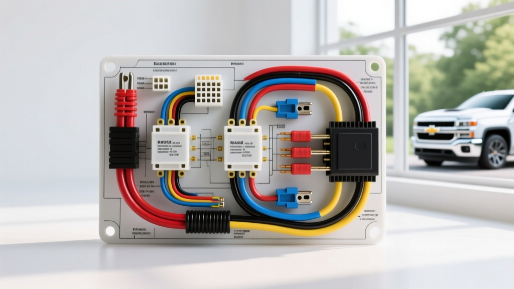
The Trap of Generic Free Wiring Schematics for Cars
When searching for free wiring schematics for cars, DIYers and independent technicians often stumble upon generic, outdated, or incomplete diagrams hosted on enthusiast forums. While these schematics can provide a basic overview of a circuit, they frequently omit critical details such as splice pack locations, exact connector cavity numbers, ground distribution points, and OEM-specific redundancy circuits. Relying on incomplete diagrams is the leading cause of misdiagnosed 'failed' fuel pumps, resulting in unnecessary parts replacement and dropped fuel tanks.
To demonstrate a professional, step-by-step troubleshooting flow, this guide utilizes the fuel pump control circuit of the 2007-2013 Chevrolet Silverado 1500 (GMT900 platform) equipped with the 5.3L V8. We will bridge the gap between generic diagrams and factory service manual (FSM) depth, focusing on wire colors, AWG specifications, and PCM logic.
Phase 1: Symptom Isolation Decision Tree
Before touching a multimeter, you must isolate the exact failure mode. Use this decision tree to determine your diagnostic path based on the vehicle's behavior during a Key-On-Engine-Off (KOEO) and cranking event.
- Symptom: Crank, No-Start (Engine turns over but does not fire)
- Does the fuel pump audibly prime for 2 seconds at KOEO?
- YES: Fuel pump control circuit is functional. Proceed to check fuel pressure regulator, injector pulse, and spark.
- NO: Proceed to Phase 2 (Schematic Decoding) and Phase 3 (Active Circuit Testing).
- Does the fuel pump audibly prime for 2 seconds at KOEO?
- Symptom: Engine starts, then immediately stalls after 2 seconds
- Diagnosis: PCM is commanding the prime, but the relay latch circuit or run-state power feed is failing. Check Fuel Pump Relay contacts and PCM ground logic.
- Symptom: Vehicle runs fine, but fuel pump runs continuously with Key OFF
- Diagnosis: Fuel Pump Relay contacts are internally welded/closed. Replace relay immediately to prevent battery drain and fire hazard.
Phase 2: Schematic Decoding and Pinout Reference
Accurate troubleshooting requires knowing exactly which wire does what. Generic free wiring schematics for cars often label wires simply as 'Power' or 'Ground'. Below is the exact OEM pinout and wire specification table for the GMT900 Silverado fuel pump circuit, adhering to SAE J1128 Low Tension Primary Cable standards for chassis and engine bay wiring.
| Component | Connector / ID | Pin | Wire Color | AWG | Function & Notes |
|---|---|---|---|---|---|
| Fuel Pump Relay | Underhood Fuse Block (X1) | 30 | ORN (Orange) | 12 | Constant Battery Feed (Hot at all times) |
| Fuel Pump Relay | Underhood Fuse Block (X1) | 87 | GRY (Gray) | 14 | Switched Power Feed to Fuel Pump |
| Fuel Pump Relay | Underhood Fuse Block (X2) | 85 | DK GRN (Dark Green) | 18 | PCM Relay Control (Ground Switch) |
| Fuel Pump | Tank Harness (C305) | A | GRY (Gray) | 14 | 12V Input from Relay |
| Fuel Pump | Tank Harness (C305) | B | BLK (Black) | 14 | Main Ground (Routes to G402) |
| EOP Switch | Engine Block Sensor | - | TAN/WHT (Tan/White) | 16 | Redundancy Power Feed (Bypass Relay) |
Phase 3: Step-by-Step Active Circuit Testing
According to Haynes fuel pump diagnostic procedures, testing must be done dynamically. A static resistance check of the pump motor is insufficient because it does not account for voltage drop under load or commutator wear.
Step 1: The 2-Second KOEO Prime Test
Turn the ignition to the ON position (do not crank). The PCM will ground the Dark Green (Pin 85) wire at the relay for exactly 2 seconds to prime the fuel rail. Listen at the fuel filler neck with the cap removed. If you hear the whine of the pump, your control circuit and pump motor are fundamentally intact. If silent, proceed to Step 2.
Step 2: Verify PCM Control Logic
Connect a digital multimeter (DMM) set to DC Volts. Backprobe the Dark Green wire at the relay socket (Pin 85). Connect the red lead to the wire and the black lead to a known good battery ground. At KOEO, you should see 12V for 2 seconds, dropping to 0V. If the voltage never drops, the PCM driver is shorted. If you never see 12V, you have an open circuit between the relay and PCM Connector X2, Pin 23.
Step 3: Voltage Drop Testing Under Load
This is where most DIYers fail. A wire can show 12V with no load, but collapse under the 8-10 Amp draw of a fuel pump. As noted in Delphi Technologies fuel system technical bulletins, excessive voltage drop causes pump cavitation, low fuel pressure, and premature motor failure.
- Power Side Drop: Place your DMM red lead on the battery positive terminal and the black lead on the Gray wire at the fuel pump connector (Pin A). Crank the engine. A reading above 0.2V indicates high resistance in the Orange feed, relay contacts, or Gray feed wire.
- Ground Side Drop: Place your DMM black lead on the battery negative terminal and the red lead on the Black ground wire at the pump connector (Pin B). Crank the engine. A reading above 0.1V indicates a corroded ground. On the GMT900, this is almost always ground point G402, located on the rear crossmember near the spare tire, which is highly susceptible to road salt and moisture intrusion.
Phase 4: The GM Oil Pressure Switch Redundancy (The 'Gotcha' Circuit)
One of the most critical details omitted from generic free wiring schematics for cars is the GM LS-engine fuel pump redundancy circuit. GM designed the Engine Oil Pressure (EOP) switch to act as a fail-safe. If the fuel pump relay fails or the PCM loses control of the ground circuit, the EOP switch will power the fuel pump directly once oil pressure reaches approximately 4 PSI during cranking.
How it works: The EOP switch receives battery voltage via a Pink/Black wire. When oil pressure builds, the switch closes, sending 12V down the Tan/White wire, which splices directly into the Gray fuel pump feed wire.
Troubleshooting Insight: If a customer complains that their Silverado 'cranks for a long time before starting,' but eventually runs fine, the fuel pump relay is likely dead. The PCM 2-second prime fails (no relay), but once the engine cranks long enough to build 4 PSI of oil pressure, the EOP switch closes, powers the pump, and the engine fires. Diagnosing this without a complete OEM schematic often leads technicians to incorrectly replace the fuel pump module or the PCM.
Summary and Repair Best Practices
When repairing the GMT900 fuel pump circuit, always use a proper fuel pump module lock ring tool and torque the retaining ring to 25 Nm (18 lb-ft) to prevent EVAP leaks and fuel vapor venting. When repairing the G402 ground, do not simply sand the surface; use a dielectric compound after securing the star washer to the bare metal frame to prevent future galvanic corrosion. By moving beyond basic free wiring schematics for cars and utilizing OEM-level pinouts, voltage drop testing, and redundancy logic, you can accurately diagnose electrical faults on the first attempt.