Why Modern Vehicles Complicate Aftermarket Lighting Mods
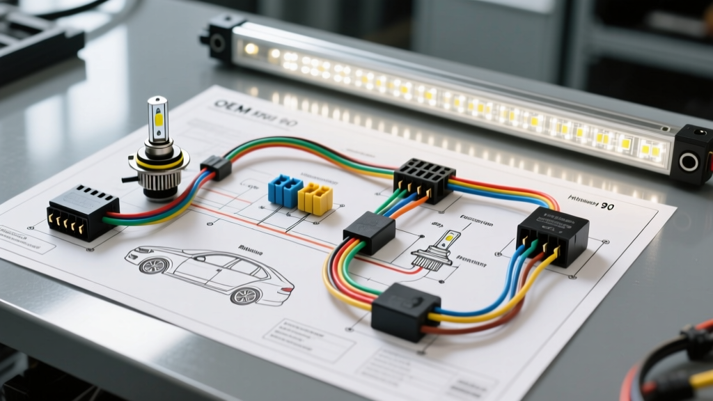
Upgrading your vehicle with auxiliary off-road lighting or high-output LED headlight bulbs is one of the most popular modification projects in the automotive world. However, modern trucks and SUVs no longer use simple analog switches to route 12V power directly from the battery to the headlight bulbs. Instead, the Body Control Module (BCM) or a dedicated lighting control module manages headlamp circuits using multiplexed networks, Pulse Width Modulation (PWM), and cold/warm diagnostic checks. If you attempt to splice a high-draw LED light bar directly into the factory headlight harness without consulting the correct schematic, you risk triggering a BCM fault code, melting a factory wire harness, or causing severe hyper-flashing. To execute a flawless upgrade, you must understand how to interpret the factory wiring diagram for car lights and use it to design a safe, isolated relay harness.
How to Read an OEM Wiring Diagram for Car Lights
When planning an auxiliary light bar installation, the goal is to find a reliable 'trigger' wire that receives 12V+ only when the driver activates a specific switch—usually the high beams. For this guide, we will use the ubiquitous dual-bulb headlight configuration found on countless modern trucks (such as the GM Silverado, Toyota Tacoma, and Ford F-150), which utilizes an H11 bulb for low beams and a 9005 (HB3) bulb for high beams.
Identifying the High-Beam Trigger (9005/HB3)
By pulling the OEM service manual schematic for the 9005 high-beam circuit, you will notice the connector features two primary pins. Pin 1 is the switched 12V+ power feed originating from the BCM or headlamp relay, while Pin 2 is the chassis ground. In many GM applications, the 12V+ trigger wire is Dark Green or Red/White, and the ground is Black. The wiring diagram confirms that this circuit is isolated from the low-beam circuit, making it the perfect trigger source for an auxiliary light bar relay. You will use a Posi-Tap connector to safely interface with this wire without severing the OEM harness.
Identifying the Low-Beam Power Source (H11)
The H11 low-beam circuit operates similarly but is often subjected to PWM (Pulse Width Modulation) if the vehicle uses the low beams as Daytime Running Lights (DRLs). A multimeter might read an average of 6V to 9V on this wire during the day, which is insufficient to reliably hold a standard 12V automotive relay closed. Therefore, the wiring diagram dictates that the high-beam (9005) circuit is the superior, stable 12V trigger source for auxiliary lighting modifications.
Designing the Relay Harness: AWG and Pinout Specifications
A 50-inch LED light bar typically draws between 12A and 18A. Running this current through the factory 9005 headlight wire (which is often 18 AWG or 20 AWG) will cause severe voltage drop and potentially start an electrical fire. According to SAE J1128 standards for low-tension primary automotive cable, wire gauge must be selected based on current draw and circuit length to keep voltage drop below 3%.
To solve this, we use a standard Bosch-style ISO 5-pin relay to isolate the high-current light bar circuit from the low-current OEM trigger circuit. Below is the exact pinout and wire gauge specification for your custom harness.
| Relay Pin | Function | Wire Color | AWG Size | Connection Point |
|---|---|---|---|---|
| 30 | High-Current Power In | Red | 10 AWG | Positive Battery Terminal (via 30A Inline AGU Fuse) |
| 87 | High-Current Power Out | Red | 12 AWG | LED Light Bar Positive Input |
| 85 | Low-Current Trigger In | Blue | 18 AWG | OEM 9005 High-Beam 12V+ Wire (via Posi-Tap) |
| 86 | Relay Coil Ground | Black | 16 AWG | Clean Chassis Ground or Battery Negative |
| 87a | N/C (Not Used) | N/A | N/A | Tape off and secure (Used for headlight upgrade mods) |
Step-by-Step Integration Using Posi-Taps
Once you have mapped out the wiring diagram for car lights and assembled your relay harness, follow these steps for a factory-grade installation:
- Disconnect the Battery: Always isolate the negative terminal before working near the BCM or headlamp harnesses to prevent accidental short circuits.
- Access the 9005 Connector: Remove the passenger-side headlight assembly or reach through the wheel well access panel to locate the 9005 high-beam connector.
- Install the Posi-Tap: Strip a small window in the insulation of the OEM 12V+ trigger wire. Insert it into the main barrel of the Posi-Tap, twist the cap to pierce the wire cleanly, and screw in the 18 AWG blue trigger wire (Pin 85) into the top of the tap.
- Route the 10 AWG Power Wire: Run the heavy-gauge power wire from the battery to the front grille or bumper where the light bar is mounted. Ensure it is wrapped in split-loom tubing and secured away from exhaust headers and steering linkages.
- Install the Inline Fuse: Crimp the AGU fuse holder onto the 10 AWG wire within 6 inches of the positive battery terminal. Do not install the fuse until all ground connections are finalized.
- Ground the Light Bar and Relay: Use a 12 AWG black wire to ground the light bar's negative lead to a bare-metal chassis point. Sand away paint and apply dielectric grease to prevent corrosion.
Diagnosing PWM and CANbus Interference
Even when following the wiring diagram perfectly, modern vehicles equipped with CANbus lighting networks or PWM DRL circuits can cause auxiliary lights to flicker or strobe. This happens because the BCM sends rapid voltage pulses to check for bulb continuity (Cold Diagnostics) or monitors voltage drops to detect blown bulbs (Warm Diagnostics). Because an LED relay coil draws significantly less current than a 65W halogen 9005 bulb, the BCM may interpret the relay as a 'burnt out bulb' and cut power or strobe the circuit.
Symptom-Cause-Fix Diagnostic Tree
- Symptom: Light bar flashes rapidly when first turned on, then stays solid.
- Cause: BCM Cold Diagnostic pulse.
- Fix: Install a 4700µF 25V electrolytic capacitor across the relay trigger wires (Pins 85 and 86) to absorb the pulse and maintain coil voltage.
- Symptom: Light bar strobes continuously while the high beams are on.
- Cause: The high beams are being driven by a PWM signal for DRL functionality, or the BCM is actively pulsing the circuit for Warm Diagnostics.
- Fix: Wire an aftermarket CANbus anti-flicker module (which contains heavy-duty resistors and capacitors) inline between the OEM trigger wire and Relay Pin 85.
- Symptom: The relay clicks rapidly, but the light bar does not turn on.
- Cause: Voltage drop across the 18 AWG trigger wire or a poor chassis ground on Pin 86 causing the relay coil to chatter.
- Fix: Verify chassis ground continuity. If the ground is clean, upgrade the trigger wire to 16 AWG or run a dedicated 12V+ trigger directly from an ignition-switched fuse in the engine bay fuse box using an Add-A-Circuit tap.
Protecting the BCM from Inductive Kickback
When a relay coil is de-energized (when you turn off the high beams), the collapsing magnetic field generates a high-voltage transient spike known as inductive kickback. If this spike travels back down the 18 AWG trigger wire into the BCM, it can permanently damage the solid-state lighting driver. As detailed in Littelfuse's automotive relay suppression guidelines, it is highly recommended to use a relay with an internal flyback diode or a suppression resistor built into the coil circuit. If your relay lacks this, solder a 1N4007 diode across Pins 85 and 86, with the diode's cathode (the striped end) facing the 12V+ trigger source. This safely recirculates the voltage spike and protects your vehicle's expensive lighting control modules.
By treating the factory wiring diagram for car lights as a blueprint rather than a suggestion, you ensure your auxiliary lighting modifications are robust, reliable, and completely isolated from the vehicle's sensitive multiplexed networks. For further reading on advanced automotive lighting circuits and bulb technologies, refer to the Hella Technical Portal, which offers extensive documentation on OEM lighting architectures and LED retrofitting parameters.