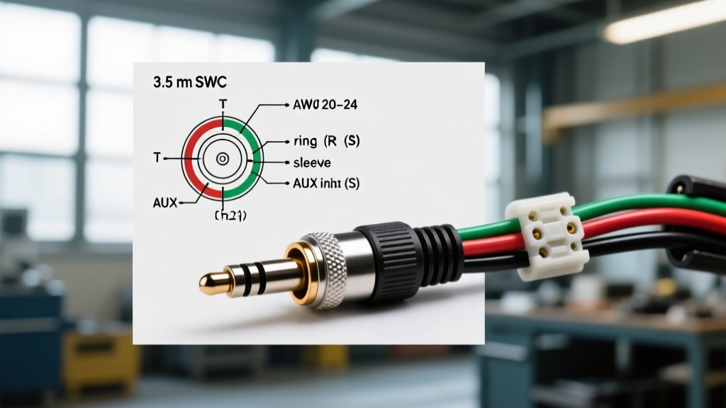
Understanding the Automotive 3.5 mm Jack
In modern automotive electrical systems and aftermarket car audio installations, the 3.5 mm jack has become the standard interface for low-voltage signal transmission. While originally designed for consumer audio, the automotive industry has repurposed this connector for critical data and control signals. When consulting a wiring diagram 3.5 mm jack for vehicle applications, technicians are primarily dealing with two systems: Steering Wheel Control (SWC) interfaces and Auxiliary (AUX) media inputs. Aftermarket head unit manufacturers like Pioneer, Kenwood, and Alpine utilize the 3.5 mm TRS (Tip-Ring-Sleeve) jack to receive analog resistance data from the vehicle's steering wheel buttons or to accept auxiliary audio/video signals. Understanding the exact pinout, wire gauge requirements, and signal translation protocols is essential for preventing short circuits, ground loops, and module failure.
Standard TRS and TRRS Pinout Configurations
Before splicing into any vehicle harness, you must identify whether your 3.5 mm connector is a TRS (3-pole) or TRRS (4-pole) configuration. Automotive SWC interfaces almost exclusively use the TRS layout, while AUX input pigtails may use TRRS to accommodate stereo audio and a video trigger.
| Pole Type | Tip (T) | Ring 1 (R1) | Ring 2 (R2) | Sleeve (S) | Primary Automotive Use |
|---|---|---|---|---|---|
| TRS (3-Pole) | SWC 1 (Key 1) / Left Audio | SWC 2 (Key 2) / Right Audio | N/A | Signal Ground | Steering Wheel Controls, Standard AUX |
| TRRS (4-Pole) | Left Audio | Right Audio | Video / Remote Turn-On | Signal Ground | OEM AUX/USB Hubs, Backup Camera Triggers |
According to Crutchfield's Steering Wheel Control Database, the most common failure point in SWC integration is swapping the Tip and Ring 1 wires. In a standard Pioneer or Kenwood SWC harness, Tip corresponds to SWC 1 (usually handling Volume and Mode), while Ring 1 corresponds to SWC 2 (handling Seek and Preset). The Sleeve must always be tied to a clean, dedicated signal ground, not a high-current chassis ground, to prevent alternator whine.
Steering Wheel Control (SWC) Integration Walkthrough
Integrating a 3.5 mm jack into a vehicle's SWC circuit requires translating the mechanical button presses on the steering wheel into electrical signals the aftermarket radio can read. This is achieved through one of two primary architectures: Resistor Ladders or CAN-Bus decoding.
Resistor Ladder Vehicles (Pre-2010 Models)
In older vehicles (commonly found in Toyota, Honda, and GM platforms prior to 2010), the steering wheel buttons act as switches that route current through specific resistors. The 3.5 mm jack wiring diagram for these vehicles maps directly to the analog output of an SWC interface module like the PAC SWI-JACK. The interface module reads the vehicle's resistance and outputs a corresponding resistance to the 3.5 mm jack.
- Volume Up: 0 Ohms (Direct Short to Ground via Tip)
- Volume Down: 300 Ohms
- Mode/Source: 1,000 Ohms
- Seek Up: 3,000 Ohms (via Ring 1)
- Seek Down: 5,200 Ohms
When wiring the 3.5 mm pigtail to the interface module, ensure the module's internal DIP switches are programmed to match the target radio's resistance map. If the Tip and Ring wires are reversed at the 3.5 mm jack, the radio will interpret Volume commands as Seek commands.
CAN-Bus Vehicles (2010-Present)
Modern vehicles utilize a Controller Area Network (CAN-Bus) to transmit steering wheel commands digitally. The physical buttons do not change resistance; instead, they send a digital hex code across the CAN-High and CAN-Low twisted pair wires. In this scenario, the 3.5 mm jack does not connect directly to the vehicle. Instead, it connects to a CAN-Bus decoder module (e.g., Axxess ASWC-1 or PAC RP5-CH11). The decoder intercepts the digital CAN messages, translates them into an analog resistance or voltage pulse, and outputs that signal through the 3.5 mm TRS jack to the aftermarket radio. The wiring diagram for the 3.5 mm jack remains identical to the resistor ladder setup, but the wiring on the vehicle side of the module requires tapping into the OBD-II port or the body control module (BCM) CAN wires using T-taps or Posi-Taps.
Wire Specifications and Soldering Protocols
Because the 3.5 mm jack handles low-voltage, low-current analog signals, wire selection is critical to prevent voltage drop and electromagnetic interference (EMI). According to the SAE J1128 Low-Tension Primary Cable Standard, signal wires should be stranded, bare copper with thin-wall insulation.
| Wire Function | Recommended AWG | Wire Type | Shielding Requirement |
|---|---|---|---|
| Tip (SWC 1 / Audio L) | 22 AWG | Stranded Copper (SAE J1128) | Unshielded (if routed away from power) |
| Ring (SWC 2 / Audio R) | 22 AWG | Stranded Copper (SAE J1128) | Unshielded (if routed away from power) |
| Sleeve (Signal Ground) | 18 AWG | Stranded Copper (SAE J1128) | Shielded / Braided Drain Wire |
Soldering the 3.5 mm Jack: The internal housing of most automotive-grade 3.5 mm pigtails uses ABS or polycarbonate plastics with low melting points. Applying a 40-watt soldering iron directly to the solder cups for more than three seconds will melt the internal dielectric separator, causing a permanent short between the Tip and Ring. To prevent this, strip and tin your 22 AWG wires with 60/40 rosin-core solder before attempting to join them to the jack. Use a hemostat or alligator clip clamped to the wire between the solder cup and the plastic housing to act as a heat sink, drawing thermal energy away from the plastic.
Clock Spring and Rotary Coupler Integrity
A wiring diagram 3.5 mm jack guide is incomplete without addressing the vehicle's clock spring (rotary coupler). The clock spring is the mechanical ribbon cable that maintains electrical continuity between the stationary steering column and the rotating steering wheel. The SWC signals must pass through this ribbon cable before reaching the 3.5 mm interface harness. If the clock spring is damaged, or if the steering wheel was removed and reinstalled without locking the clock spring in its center position, the internal ribbon will snap. Symptoms of a broken clock spring include non-functional SWC buttons, an illuminated SRS/Airbag light, and a non-functional horn. Always verify clock spring continuity with a multimeter before blaming the 3.5 mm jack wiring or the interface module.
Troubleshooting Decision Tree
When the 3.5 mm jack integration fails to operate as expected, use this diagnostic sequence to isolate the fault:
- Symptom: Alternator Whine in AUX Audio.
- Cause: Ground loop. The 3.5 mm Sleeve ground is sharing a path with high-current amplifier grounds.
- Fix: Relocate the 3.5 mm Sleeve ground to a dedicated 'star ground' point behind the dashboard, isolated from the chassis and amplifier power grounds. Install an inline ground loop isolator if necessary.
- Symptom: Volume Buttons Trigger Track Skip.
- Cause: Tip and Ring 1 wires are reversed at the 3.5 mm plug or the interface module.
- Fix: Use a multimeter in continuity mode to trace the Tip and Ring back to the SWC 1 and SWC 2 pins on the module. Swap the connections.
- Symptom: Intermittent Button Response or 'Stuck' Commands.
- Cause: Partial short between Tip and Ring due to melted plastic inside the 3.5 mm jack, or frayed wires inside the steering column clock spring.
- Fix: Disconnect the 3.5 mm jack and measure resistance across Tip and Ring with no buttons pressed. It should read infinite (OL). If it reads low resistance, replace the pigtail. If the pigtail tests fine, inspect the clock spring harness.
By adhering to these precise pinout configurations, SAE wire standards, and soldering protocols, you can ensure a reliable, noise-free integration of 3.5 mm jack interfaces in any automotive environment.