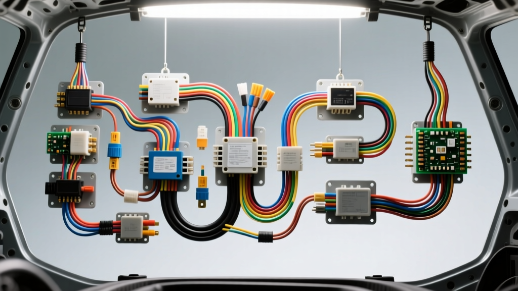
Introduction: Bridging Residential and Automotive Electrical Systems
When transitioning from residential DIY projects to automotive upfits, beginners often search for an electrical wiring diagram house guide, only to realize that the rules of residential alternating current (AC) do not directly apply to direct current (DC) vehicle systems. In the realm of Recreational Vehicles (RVs), camper vans, and overland rigs, you are actually dealing with two distinct electrical environments: the chassis (the vehicle's engine, ECU, and starting battery) and the house (the living area's 12V DC and 120V AC loads). Understanding how to read and integrate an automotive wiring diagram with a residential-style house diagram is the most critical fundamental for any beginner auto-electrician.
While a standard home relies on 120V/240V AC power routed through a centralized breaker panel, a vehicle operates on a 12V or 24V DC negative-ground system. Misapplying residential wiring logic to a vehicle chassis can result in catastrophic voltage drop, melted insulation, or electrical fires. This guide breaks down the fundamental differences between house and automotive wiring, providing the technical specifications needed to safely design and troubleshoot dual-system RV diagrams.
Wire Construction: NEC THHN vs. SAE J1128
The most common mistake beginners make when building a camper van is using solid-core residential Romex or THHN wire for 12V DC chassis and house battery runs. Residential wire is designed to be pulled through stationary PVC conduit and is entirely unsuited for the high-vibration, high-heat environment of a vehicle.
Automotive wiring must comply with SAE International J1128 standards. Wire types like GXL (General Cross-Linked) and TXL (Thin-wall Cross-Linked) feature highly stranded copper cores and cross-linked polyethylene (XLPE) insulation. This allows the wire to flex continuously without breaking the copper strands and withstand under-hood temperatures up to 125°C (257°F). In contrast, standard house wire insulation becomes brittle and cracks when subjected to engine bay heat and chassis vibration.
| Specification | Residential House Wire (THHN) | Automotive Chassis Wire (GXL) |
|---|---|---|
| Current Type | AC (Alternating Current) | DC (Direct Current) |
| Conductor Stranding | Solid or Coarse (7-19 strands) | Fine (41-259+ strands) |
| Insulation Material | PVC / Nylon | Cross-Linked Polyethylene (XLPE) |
| Max Temperature | 90°C (194°F) | 125°C (257°F) |
| Vibration Resistance | Poor (Prone to work-hardening) | Excellent (Highly flexible) |
The RV Split System: Chassis vs. House Diagrams
In an RV electrical wiring diagram, the system is divided into two isolated networks that must communicate without draining the vehicle's starting battery. The Chassis System powers the engine ECU, fuel injectors, headlights, and alternator. The House System powers interior LED lights, water pumps, 12V compressor fridges, and inverters.
Connecting the Systems: The Voltage Sensitive Relay (VSR)
To bridge these two systems safely, modern diagrams utilize a Voltage Sensitive Relay (VSR) or a Battery Isolator. When the engine starts, the alternator raises the chassis battery voltage to approximately 13.7V - 14.4V. The VSR detects this threshold and closes an internal heavy-duty solenoid, connecting the chassis battery to the house battery bank to charge it. When the engine shuts off and voltage drops below 12.8V, the VSR opens, isolating the batteries so your house loads cannot strand you with a dead starter battery.
Typical VSR Wiring Pinout (e.g., Blue Sea Systems 7610):
- Stud A (Large): Connected to Chassis Battery Positive (1/0 AWG)
- Stud B (Large): Connected to House Battery Bank Positive (1/0 AWG)
- Pin 1 (Small): Ignition Signal (Optional, 16 AWG Red)
- Pin 2 (Small): Ground Override (Optional, 16 AWG Black)
- Case Ground: Must be grounded directly to the chassis frame (10 AWG Black)
AWG Sizing: The 12-Volt Reality Check
Because Power (Watts) = Voltage x Current (Amps), operating at 12V DC requires significantly more amperage to deliver the same wattage as a 120V AC house circuit. This drastically increases the required American Wire Gauge (AWG) thickness to prevent voltage drop and resistive heating.
For example, a 1200W microwave on a 120V house circuit draws only 10 Amps, requiring standard 14 AWG residential wire. However, a 1200W inverter running off a 12V house battery draws 100 Amps (plus inefficiency losses, pushing it closer to 115 Amps). Running 115 Amps through 14 AWG wire will instantly melt the insulation and cause a fire. For a 3-foot run at 120A with a 3% allowable voltage drop, you must use 1/0 AWG fine-strand automotive cable.
Always calculate wire size based on the one-way distance from the power source to the load, multiplied by two (to account for the return ground path), and reference the National Electrical Code (NEC) Chapter 9, Table 8 for DC resistance values, adjusting for the SAE 12V standard.
Standardizing Color Codes: NEC vs. SAE
Reading an automotive schematic requires unlearning residential color codes. In house wiring, Black is Hot, White is Neutral, and Green/Bare is Ground. In automotive DC wiring, there is no 'neutral'; the circuit is completed via the vehicle's steel chassis or a dedicated negative return wire.
| Function | Residential House (NEC AC) | Automotive / RV House (SAE DC) |
|---|---|---|
| Main Power / Hot | Black or Red | Red (Battery +) |
| Ground / Neutral | White (Neutral) / Bare (Ground) | Black or White (Battery - / Chassis Ground) |
| Switched / Accessory | Red or Blue (Travelers) | Yellow or Blue (12V Ignition/Accessory) |
| Data / CAN Bus | Cat5e / Cat6 (Ethernet) | Twisted Pair (Often Green/White or Purple) |
Note: The RV Industry Association (RVIA) mandates that in RV 120V AC house wiring, standard residential NEC color codes must be strictly followed to prevent lethal AC/DC cross-wiring accidents.
The 7-Pin RV Connector: Where House Meets Vehicle
When towing a trailer, the 7-pin connector (SAE J286 standard) is the physical bridge between the tow vehicle's chassis diagram and the trailer's house diagram. Understanding this pinout is essential for troubleshooting trailer brake and lighting failures.
| Pin | Function | Wire Color | Min. AWG |
|---|---|---|---|
| 1 | Ground Return (Chassis) | White | 10 AWG |
| 2 | 12V Auxiliary (House Battery Charge) | Black | 10 AWG |
| 3 | Tail / Running Lights | Brown | 16 AWG |
| 4 | Left Turn / Stop | Yellow | 16 AWG |
| 5 | Right Turn / Stop | Green | 16 AWG |
| 6 | Electric Trailer Brakes | Blue | 12 AWG |
| 7 | Backup Lights / Reverse Lockout | Purple | 16 AWG |
Grounding: The Ultimate Beginner Pitfall
In residential house wiring, the neutral and ground are bonded at the main service panel. In a vehicle, the entire steel chassis acts as the negative return path for the chassis system. However, for the RV 'house' system, relying on the chassis frame for high-amperage DC returns (like an inverter or water heater) is a major failure point due to rust, paint, and dissimilar metal corrosion.
Best Practice for House Diagrams: Run dedicated negative return wires (White or Black SAE GXL) from all major house loads back to a centralized, isolated negative busbar. This busbar should then be connected to the house battery bank's negative terminal. The only connection between the house negative bus and the vehicle chassis should be a single, heavy-gauge bonding wire (e.g., 2 AWG) to equalize potential and prevent static buildup, ensuring your ECU and sensitive CAN-bus modules are not subjected to stray 12V house currents.
Termination Standards
Never use wire nuts or push-in residential connectors in a vehicle. All automotive and RV house wiring must be terminated using adhesive-lined heat shrink ring terminals, crimped with a ratcheting crimper calibrated for the specific AWG. This creates a gas-tight seal that prevents moisture intrusion and terminal oxidation, ensuring the integrity of your electrical diagram for years on the road.