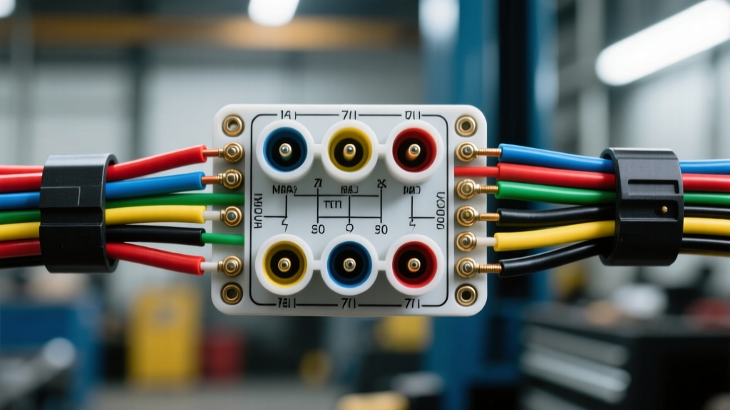
Mastering the Electric Brake Wiring Diagram Trailer Diagnostic Flow
When a trailer's braking system fails or behaves erratically, guessing is not an option. A systematic approach based on a precise electric brake wiring diagram trailer schematic is the only safe way to isolate faults. Whether you are dealing with a weak braking response, a completely dead axle, or a parasitic draw tripping your tow vehicle's brake controller, this step-by-step troubleshooting flow will guide you from the 7-way connector to the individual brake magnets.
This guide assumes a standard 7-way RV blade connector and a 12-volt DC electric brake system utilizing 10 AWG and 12 AWG copper wiring. We will cover voltage testing, resistance diagnostics, and common OEM wiring discrepancies.
Reference: Standard 7-Way RV Blade Pinout & Wire Specifications
Before beginning diagnostics, verify your baseline. According to the etrailer Wiring Standards Guide, the industry-standard 7-way connector utilizes specific color codes. However, always test with a multimeter, as aftermarket molded pigtails frequently violate these color conventions.
| Function | Standard Wire Color | AWG Size (Min) | Max Ampacity |
|---|---|---|---|
| Ground Return | White | 10 AWG (or 8 AWG) | 40A |
| Tail / Running Lights | Brown | 16 AWG | 10A |
| Left Turn / Stop | Yellow | 16 AWG | 10A |
| Right Turn / Stop | Green | 16 AWG | 10A |
| Electric Brake Output | Blue | 10 AWG | 30A |
| 12V Auxiliary / Battery Charge | Black | 10 AWG | 30A |
| Reverse Lights / Aux | Purple | 16 AWG | 10A |
Step 1: Verify Tow Vehicle Output (The Source)
Troubleshooting must always begin at the source. A failure at the trailer plug is often misdiagnosed when the tow vehicle's brake controller or wiring harness is actually at fault.
Testing the Controller Output
- Preparation: Connect the trailer to the tow vehicle. Ensure the tow vehicle ignition is ON and the brake controller (e.g., Tekonsha Prodigy P3 or Redarc Tow-Pro) is powered.
- Multimeter Setup: Set your digital multimeter (DMM) to DC Voltage. Insert the black probe into the White (Ground) pin and the red probe into the Blue (Electric Brake) pin on the vehicle-side 7-way receptacle.
- Manual Override Test: Slide the manual override lever on the brake controller to maximum. You should read between 11.5V and 12.2V. If you read 0V, the fault is in the tow vehicle (blown 30A inline fuse, faulty controller, or severed blue wire under the dash).
- Pedal Test: Press the tow vehicle brake pedal. Voltage should scale smoothly from 0V up to 12V based on the controller's gain setting.
Expert Insight: If voltage fluctuates wildly or drops below 10V under load, inspect the 30-amp circuit breaker located near the vehicle's battery. Thermal breakers can fatigue and trip prematurely under sustained amperage draws.
Step 2: Diagnose the Trailer 7-Way Connector & Junction Box
If the tow vehicle is outputting correct voltage, move to the trailer side. Modern trailers route the 7-way molded pigtail into a front-mounted junction box rather than splicing directly into the chassis harness.
The Junction Box Voltage Drop Test
Corrosion inside the junction box terminal block is a leading cause of weak trailer brakes. With the trailer connected and the manual override engaged:
- Open the junction box and locate the terminal labeled 'EB' or 'Brakes' (typically where the Blue wire terminates).
- Measure DC voltage between this terminal and the main White ground bus bar.
- Calculate Voltage Drop: Compare this reading to the voltage at the vehicle's 7-way plug. A drop greater than 0.5V indicates high resistance. This is usually caused by oxidized ring terminals or undersized wiring.
According to Tekonsha Technical Resources, electric brake systems require robust grounding. If the White ground wire from the 7-way plug to the junction box is only 12 AWG, upgrade it to 10 AWG or 8 AWG to eliminate ground-bottlenecking.
Step 3: Trace the Axle Wiring and Breakaway Switch
The breakaway switch is a critical safety device wired in parallel with the main brake circuit. It draws power directly from a dedicated 12V breakaway battery (usually a 5Ah SLA battery) to lock the brakes if the trailer separates.
Breakaway Switch Decision Tree
- Symptom: Trailer brakes lock up randomly while driving, or tow vehicle controller displays a 'SH' (Short) or 'OL' (Overload) code.
- Check 1: Is the breakaway pin fully seated in the switch housing? A bent pin or a failing microswitch can intermittently close the circuit.
- Check 2: Inspect the breakaway switch wiring. One wire goes to the positive terminal of the breakaway battery; the other splices into the Blue brake output wire. If the insulation on the switch wire is chafed against the chassis, it will short to ground, sending 12V directly to the magnets and bypassing the controller.
- Fix: Replace the switch if continuity tests fail. Route wires through split-loom tubing and secure with UV-resistant zip ties away from the tongue jack mechanism.
Step 4: Test the Brake Magnets and Drums
If voltage is reaching the trailer's rear junction or axle pigtails but braking is weak or non-existent, the issue lies at the wheels. Electric brake systems use 12-inch or 10-inch electromagnets that press against the inner drum face to actuate the brake shoes.
Measuring Magnet Resistance (Ohms)
Disconnect the trailer from the tow vehicle to prevent back-feeding voltage into the controller. Set your DMM to Ohms (Ω).
| Magnet Size | Expected Resistance (Per Magnet) | Total Parallel Resistance (Tandem Axle / 4 Magnets) |
|---|---|---|
| 10-Inch Magnet | 3.8 - 4.5 Ω | 0.95 - 1.12 Ω |
| 12-Inch Magnet | 3.0 - 3.8 Ω | 0.75 - 0.95 Ω |
- At the wheel, disconnect the two wires feeding the brake magnet (usually Blue and White, though some OEMs use Black and White).
- Place probes on the two magnet leads. If the reading is 'OL' (Open Line), the internal copper windings are broken. The magnet must be replaced.
- If the reading is near 0.0 Ω, the magnet is internally shorted.
- Ground Short Test: Place one probe on a magnet lead and the other on the bare metal axle or brake backing plate. The reading must be 'OL'. If you read continuity, the magnet casing has worn through and is shorting against the drum or backing plate.
Step 5: Inspect Physical Drum Wear and Armature Faces
Electrical diagnostics mean nothing if the mechanical components are compromised. Pull the hub and drum assembly off the spindle to inspect the armature (the flat surface inside the drum where the magnet rides).
- Cone-Shaped Wear: If the armature surface is deeply grooved or cone-shaped, the magnet has worn unevenly. Even if the magnet passes an Ohms test, it will not generate sufficient electromagnetic friction. Replace both the drum and the magnet.
- Grease Contamination: A blown inner rear axle seal will saturate the brake shoes and magnet face in gear oil. Clean the backing plate with brake cleaner, replace the seal, and replace the grease-contaminated shoes. Magnets can sometimes be cleaned with fine sandpaper, but replacement is recommended if oil has penetrated the epoxy casing.
Common Failure Modes & Expert Fixes Summary
Use this rapid-reference matrix to shortcut your diagnostic flow based on driver-reported symptoms:
| Reported Symptom | Probable Root Cause | Targeted Fix |
|---|---|---|
| Brakes pulse or grab aggressively | Dirty or corroded 7-way ground pin (White) | Sand 7-way pins, apply dielectric grease, upgrade ground to 8 AWG |
| Controller shows 'No Trailer Connected' | Open circuit in Blue wire or burnt-out magnet | Check continuity from junction box to axle; replace open magnets |
| Brakes feel incredibly weak at max gain | Voltage drop due to undersized wiring (14/16 AWG) | Rewire main chassis harness with 10 AWG stranded copper |
| Controller displays 'SH' (Short) Error | Blue wire chafing against frame or failed breakaway switch | Inspect frame routing, test breakaway switch for internal short |
Final Verification and Road Testing
After resolving the identified fault, perform a static drag test. Jack up the trailer so all wheels are off the ground. Spin each wheel by hand while an assistant applies the manual override on the brake controller. You should feel immediate, uniform resistance across all wheels, and hear a distinct 'humming' sound from the 12V magnets engaging against the drums.
For comprehensive schematics and OEM-specific controller pinouts, always refer to the SAE J286 Trailer Connector Standards documentation and your specific brake controller manufacturer's installation addendum. Proper adherence to these electrical standards ensures not only compliance but the safety of your rig on steep grades and highway emergencies.