Upgrading Fleet Depots: The EV Power Challenge
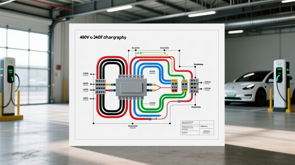
When converting a traditional diesel maintenance bay into a heavy-duty Electric Vehicle (EV) fleet depot, the electrical infrastructure is the first major bottleneck. Most industrial automotive facilities are fed with 480V three-phase power to run heavy machinery, air compressors, and overhead cranes. However, modern EV fleet diagnostic tools, Level 2 AC charging stations, and heavy-duty battery thermal management systems require 240V single-phase or 120/240V split-phase power. This is where mastering the transformer wiring diagram 480 to 240 becomes critical for your upgrade and modification project.
As an automotive electrical specialist, bridging the gap between industrial facility power and vehicle-specific diagnostic and charging equipment is a daily reality. Whether you are setting up a bay for Proterra electric transit buses, Tesla Semi diagnostics, or Ford F-150 Lightning fleet charging, the step-down transformer is the heart of your electrical modification. This guide details the exact wiring schematics, AWG sizing, and terminal configurations required to safely integrate a 480V to 240V transformer in a vehicle maintenance environment.
Decoding the Transformer Wiring Diagram 480 to 240
For automotive shop upgrades, the most common and versatile configuration is a 30kVA or 45kVA step-down transformer with a 480V Delta primary and a 240/120V Center-Tapped Split-Phase secondary. This specific topology provides 240V for high-amperage EV chargers and 120V split-phase for OEM diagnostic laptops, break-out boxes, and standard shop lighting.
According to the NFPA 70 National Electrical Code (NEC) Article 450, transformers installed in commercial automotive facilities must adhere to strict overcurrent protection and ventilation guidelines. The wiring diagram for this setup relies on specific terminal designations that differ significantly from standard 12V or 24V vehicle harness schematics.
Primary Side (480V Delta) Terminals
The primary side connects to the facility's 480V three-phase supply. Industrial automotive shops typically follow standard NEC color codes for high-voltage three-phase systems. The phase conductors are Brown (Phase A), Orange (Phase B), and Yellow (Phase C). On a standard Delta primary transformer, you will utilize terminals H1, H2, and H3. There is no neutral connection on a Delta primary, but an equipment grounding conductor (EGC) must be routed to the transformer chassis ground lug.
Secondary Side (240/120V Split-Phase) Terminals
The secondary side is where the power is adapted for vehicle-level equipment. A center-tapped split-phase secondary utilizes terminals X1, X2, X3, and X4. In this configuration, X1 and X4 are the outer phase lines (240V across them), while X2 and X3 are the center taps (providing 120V to either outer line). For a standard split-phase output, X2 and X3 are bonded together and connected to the Neutral/Ground bus bar, establishing your 120/240V split-phase system.
Wire Sizing and AWG Specifications Chart
Selecting the correct American Wire Gauge (AWG) is vital to prevent voltage drop, which can cause catastrophic failures in sensitive vehicle ECU flashing tools and EV battery management system (BMS) preconditioning cycles. The following chart outlines the specifications for copper (Cu) conductors with 75°C insulation (THHN/THWN) commonly used in liquid-tight flexible metal conduit (LFMC) in automotive bays.
| Transformer kVA | Primary Voltage | Primary Amps | Primary AWG (Cu) | Secondary Voltage | Secondary Amps | Secondary AWG (Cu) |
|---|---|---|---|---|---|---|
| 15 kVA | 480V 3-Phase | 18.0 A | 12 AWG | 240/120V Split | 62.5 A | 6 AWG |
| 30 kVA | 480V 3-Phase | 36.1 A | 8 AWG | 240/120V Split | 125.0 A | 1/0 AWG |
| 45 kVA | 480V 3-Phase | 54.1 A | 4 AWG | 240/120V Split | 187.5 A | 3/0 AWG |
| 75 kVA | 480V 3-Phase | 90.2 A | 1/0 AWG | 240/120V Split | 312.5 A | 350 kcmil |
Note: Always apply the 125% continuous load multiplier required by the NEC when sizing overcurrent protection devices (OCPD) and conductors for EV charging stations, as vehicle charging is classified as a continuous load.
Step-by-Step Wiring Guide for the Diagnostic & Charging Bay
Executing the transformer wiring diagram 480 to 240 requires precision and adherence to torque specifications. Improperly torqued lugs in an automotive shop environment—where heavy machinery and vehicle movement cause floor vibrations—will lead to thermal runaway and arcing.
1. Primary Side Connections (480V)
- Phase A (Brown): Connect to terminal H1. Torque to 25 lb-ft (for 8 AWG to 4 AWG lugs).
- Phase B (Orange): Connect to terminal H2. Torque to 25 lb-ft.
- Phase C (Yellow): Connect to terminal H3. Torque to 25 lb-ft.
- Grounding: Route a 6 AWG bare copper EGC from the facility ground bus to the transformer chassis ground lug. This is critical for clearing ground faults and protecting sensitive SAE J1772 and CCS1 vehicle communication circuits from stray voltage.
2. Secondary Side Connections (240/120V)
- Line 1 (Black): Connect to terminal X1. This provides 120V to neutral and 240V to Line 2.
- Neutral (White): Bond terminals X2 and X3 together with a jumper wire. Connect the white neutral conductor to this bonded terminal block.
- Line 2 (Red): Connect to terminal X4.
- Grounding & Bonding: The secondary neutral (X2/X3) must be bonded to the transformer chassis ground and the secondary EGC. This creates the separately derived system required by NEC Article 250.30.
Automotive Shop Safety and Grounding Considerations
In a vehicle modification and diagnostic environment, the grounding grid is just as important as the power delivery. Electric vehicles utilize high-frequency switching inverters and DC-DC converters that can introduce harmonic noise back into the shop's electrical system. If the transformer grounding is inadequate, this noise can corrupt the CAN bus signals on your diagnostic break-out boxes, leading to phantom diagnostic trouble codes (DTCs) or failed ECU flashes.
Always install a dedicated ground rod for the separately derived 240V system if permitted by local AHJ (Authority Having Jurisdiction), and ensure the grounding electrode conductor (GEC) is sized according to NEC Table 250.66. For a 1/0 AWG secondary phase conductor, a minimum 6 AWG copper GEC is required.
Troubleshooting Voltage Drop in Heavy-Duty EV Bays
When an electric transit bus or heavy-duty EV initiates a DC fast charge preconditioning cycle, the inrush current can be massive. If your transformer wiring diagram 480 to 240 was not executed with proper AWG sizing or if connections have degraded, you will experience severe voltage drop.
Common Failure Modes and Diagnostics
- Diagnostic Laptop Reboots During Vehicle Connection: If your OEM diagnostic laptop (e.g., Cummins INLINE 7 or NEXIQ USB-Link 3) reboots when an EV is plugged into the bay's Level 2 charger, you likely have a loose neutral connection on the X2/X3 terminals. The sudden load shift causes the 120V leg to sag below the 105V threshold of the laptop's power supply. Fix: Isolate power, verify X2/X3 bonding jumper, and re-torque to 40 lb-ft.
- Transformer Humming and Overheating: A loud 60Hz hum accompanied by excessive heat on the transformer casing often indicates harmonic distortion from non-linear automotive loads (like variable frequency drives on shop ventilation or EV battery cooling carts). Fix: Upgrade to a K-4 or K-13 rated transformer designed to handle automotive harmonic loads, as outlined in Schneider Electric transformer guidelines.
- EV Charger Ground Fault Errors: If the vehicle's BMS rejects the charge and throws a ground fault, the issue is often an improperly bonded secondary neutral. The vehicle's internal isolation monitor detects a floating neutral and aborts the charge for safety. Fix: Verify the X2/X3 to chassis ground bonding strap is intact and measures less than 0.5 ohms of resistance.
Final Thoughts on Fleet Power Modifications
Upgrading a fleet maintenance shop to support modern electric vehicles requires more than just running new conduit; it demands a deep understanding of industrial-to-automotive power conversion. By strictly following the transformer wiring diagram 480 to 240, utilizing the correct AWG wire sizes, and adhering to strict torque and grounding specifications, you ensure that your diagnostic bays and charging stations operate flawlessly. Proper execution not only protects your expensive automotive diagnostic equipment but also ensures the safety and longevity of the multi-million-dollar EV fleet you are tasked with maintaining.