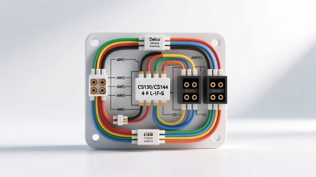
Understanding the GM Delco CS130 and CS144 4-Wire Architecture
The transition from the legendary 10-SI and 12-SI externally regulated alternators to the internally regulated CS (Charging System) series marked a massive shift in General Motors electrical architecture. When technicians and restomod builders reference a delco chevy 4 wire alternator wiring diagram, they are almost exclusively dealing with the Delco-Remy CS130, CS130D, or the larger CS144 platforms. Unlike the older 2-wire setups, the CS series utilizes a 4-pin Packard Electric (now Delphi) Metri-Pack 280 series weather-sealed connector. While not all four pins are populated in every OEM application, understanding the complete L-I-F-S matrix is critical for custom harness fabrication, LS-swaps, and OBD-II PCM integration.
This advanced technical guide bypasses basic overviews and dives directly into terminal pinouts, excitation current requirements, Pulse Width Modulation (PWM) signaling, and precise AWG specifications required to build a reliable, high-output charging system.
The 4-Pin Connector: L-I-F-S Terminal Pinout Matrix
The physical 4-way connector on the CS130/CS144 features terminals stamped directly onto the alternator housing. Below is the definitive pinout matrix for custom harness construction.
| Terminal | Designation | OEM Wire Color (Typical) | AWG Size | Circuit Function & Electrical Characteristics |
|---|---|---|---|---|
| L | Lamp | Brown or White | 18 AWG | Provides initial excitation current (20-50mA) to the internal voltage regulator. Completes ground path through dash indicator bulb. |
| I | Ignition | Pink | 18 AWG | Switched 12V source. Used on specific OEM applications to 'wake up' the regulator independently of the L circuit. Often omitted in retrofits. |
| F | Field | Gray or White | 18 AWG | PWM output signal (approx. 128 Hz, 0-5V square wave) sent to the PCM to indicate alternator load and duty cycle. |
| S | Sense | Red or Pink | 12 AWG | Reads true system voltage at the battery or main distribution block to compensate for voltage drop in the main charge cable. |
Step-by-Step Wiring Execution & AWG Requirements
Building a custom harness requires automotive-grade cross-linked polyethylene wire (TXL or GXL) and proper Delphi Metri-Pack 280 crimp terminals. Never use solder-only connections in high-vibration alternator harnesses; always use a ratcheting crimp tool designed for open-barrel terminals.
1. The Sense (S) Circuit: Voltage Drop Compensation
The most common failure in custom Delco 4-wire installations is jumpering the 'S' terminal directly to the alternator's main BATT output post. If you do this, the regulator senses 14.2V at the alternator and stops charging. However, due to resistance in the main charge cable, the battery may only see 13.4V, leading to chronic undercharging. The Fix: Run a dedicated 12 AWG TXL wire from the 'S' terminal directly to the positive battery post or the main starter solenoid stud. Critical Safety Step: You must install a 20A MAXI or MIDI inline fuse within 18 inches of the battery positive terminal on this sense wire to prevent a catastrophic harness fire in the event of a short to ground.
2. The Lamp (L) Circuit and Excitation Current
The internal voltage regulator requires a small initial current flow to 'turn on' the rotor field. In OEM wiring, this is achieved by routing the 'L' terminal through the dash charge indicator bulb to ground. If you are performing an engine swap and using LED dash indicators, the LED will not draw enough current (typically under 5mA) to excite the regulator, resulting in a no-charge condition. The Fix: If using LEDs or a standalone aftermarket gauge cluster, you must wire a 470-ohm, 1/2-watt resistor in parallel with the LED circuit, or wire the resistor between the 'L' terminal and a switched 12V ignition source to provide the necessary 20-50mA excitation bias.
3. The Field (F) and Ignition (I) Circuits
The 'I' terminal is largely redundant on standalone retrofits and can be safely capped off if the 'L' circuit is properly wired. The 'F' terminal, however, is vital for OBD-II vehicles (such as LT1, LS1, and LQ4 platforms). The PCM monitors the 128 Hz PWM signal on the 'F' wire to determine alternator load. When electrical load spikes (e.g., cooling fans engage, rear defroster turns on), the PCM uses this data to command the Idle Air Control (IAC) valve or electronic throttle body to bump the engine RPM, preventing the alternator's magnetic drag from stalling the engine.
Hardware Specifications and Torque Requirements
Improper torque on the main output post is a leading cause of melted alternator cases and voltage drop. The CS130 and CS144 utilize different stud sizes and require precise torque values.
| Component | CS130 Specification | CS144 Specification |
|---|---|---|
| BATT Post Thread | 5/16"-24 UNF | 3/8"-16 UNC |
| BATT Post Torque | 80 - 120 in-lbs | 100 - 140 in-lbs |
| Recommended Main Cable | 4 AWG (up to 105A) | 2 AWG or 1/0 AWG (130A-145A) |
| Case Through-Bolts | M6 x 1.0 (35 ft-lbs) | M6 x 1.0 (35 ft-lbs) |
Diagnostic Decision Tree: Real-World Failure Modes
When troubleshooting a Delco CS-series charging system, use this symptom-cause-fix matrix to isolate electrical faults from mechanical failures.
- Symptom: Alternator output stuck at 12.4V; dash battery light remains illuminated after engine start.
Cause: Open circuit in the 'L' wire, or burned-out dash bulb preventing excitation current.
Fix: Check continuity from the ignition switch to the 'L' pin. Verify the 470-ohm resistor (if equipped) has not failed open. - Symptom: System overcharges at 15.5V or higher, boiling the battery.
Cause: The 'S' (Sense) wire is broken, disconnected, or suffering from severe voltage drop. The regulator defaults to a fail-safe high-output internal sense mode.
Fix: Check the inline fuse on the sense wire. Measure voltage drop across the sense wire with the engine running; it should read less than 0.1V. - Symptom: High-pitched 2kHz whining noise from the alternator, followed by a sudden drop to 12.0V under heavy electrical load.
Cause: CS130 rear bearing failure causing the rotor to drag on the stator, or thermal shutdown of the internal rectifier bridge (a known design flaw in early CS130s due to poor rear cooling).
Fix: Replace the unit. For high-amperage applications, upgrade the bracketry and harness to the physically larger CS144, which features superior cooling and a heavier-duty rectifier diode trio. - Symptom: Engine idle surges or stalls when the A/C compressor engages.
Cause: PCM is not receiving the PWM load signal from the 'F' terminal.
Fix: Use an oscilloscope to verify a 0-5V, 128 Hz square wave on the 'F' circuit. Repair any chafing in the gray/white wire between the alternator and the PCM.
Authoritative References
For further validation on Delco-Remy testing procedures and OEM wiring standards, consult the following technical resources: