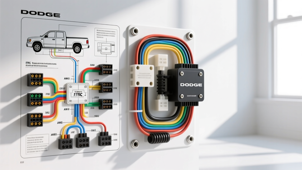
Introduction to Dodge Ram Trailer Brake Systems
When diagnosing, repairing, or upgrading the towing electrical architecture on a Dodge Ram, understanding the precise Dodge Ram trailer brake wiring diagram is critical. Modern Ram trucks (spanning the 3rd, 4th, and 5th generations from 2006 to present) utilize a complex network involving the Integrated Trailer Brake Controller (ITBC), the Totally Integrated Power Module (TIPM) or Power Distribution Center (PDC), and the rear 7-way RV blade receptacle. Unlike older vehicles that required simple analog 12-volt DC switching, modern Ram trailer brake circuits rely on Pulse Width Modulation (PWM) to deliver proportional braking force to the trailer axles. This technical specification reference provides the exact pinouts, OEM wire color codes, American Wire Gauge (AWG) requirements, and diagnostic protocols required to troubleshoot Ram trailer brake circuits accurately.
SAE J286 7-Way RV Blade Connector Pinout Specifications
The rear bumper receptacle on a factory-equipped Ram follows the SAE J286 standard for 7-way connector pinouts. However, the wire gauges and specific chassis routing colors can vary slightly between the 1500, 2500, and 3500 models. The table below outlines the standard pin configuration, OEM wire colors, and minimum AWG ratings required to prevent voltage drop under heavy braking loads.
| Pin Number | Function | OEM Wire Color | Min AWG | Technical Notes & Failure Modes |
|---|---|---|---|---|
| Pin 1 | Left Turn / Stop | Yellow | 14 AWG | Shares circuit with left tail lamp; check BCM for hyper-flash if LED trailer lights are used. |
| Pin 2 | Electric Trailer Brakes | Blue | 10 AWG | Carries the PWM signal from the ITBC. High resistance here causes weak trailer braking. |
| Pin 3 | Chassis Ground | White | 8 AWG | Critical ground return. Must be bonded directly to the truck frame, not just the bumper. |
| Pin 4 | 12V Auxiliary Power | Black | 10 AWG | Fused via TIPM/PDC relay. Powers trailer interior lights or battery charging circuits. |
| Pin 5 | Right Turn / Stop | Green | 14 AWG | Shares circuit with right tail lamp; prone to corrosion at the receptacle pigtail. |
| Pin 6 | Tail / Running Lamps | Brown | 14 AWG | Activated by the headlight switch/BCM. Verify 12V constant with parking lamps on. |
| Pin 7 | Reverse Lamps / Aux | Purple / Red | 14 AWG | Often used for trailer reverse lockout solenoids on surge brake couplers. |
Under-Dash Integrated Trailer Brake Controller (ITBC) Harness
For Rams equipped with the factory ITBC, the module is typically mounted under the driver-side dash or integrated directly into the center console stack (depending on the model year). The wiring harness connecting the ITBC to the main chassis harness utilizes a specific 4-pin or 6-pin OEM connector (often a Molex MX150 or Delphi Weather-Pack sealed interface). When referencing the Mopar Repair Connection Site schematics, the primary circuits feeding the brake controller are as follows:
- Pin A (12V Battery Feed): Red with a Black tracer (12 AWG). Provides constant 12V memory and power to the ITBC module. Fused at the PDC.
- Pin B (Brake Light Switch Signal): White with a Tan tracer (18 AWG). This is a low-current logic signal from the BCM indicating the driver has pressed the brake pedal. It triggers the ITBC to begin generating the PWM output.
- Pin C (Chassis Ground): Solid Black (12 AWG). Must have less than 0.05 ohms of resistance to the battery negative terminal.
- Pin D (Brake Output to 7-Way): Solid Blue (10 AWG). This wire routes from the ITBC, through the firewall, down the frame rail, and terminates at Pin 2 of the rear 7-way receptacle.
Totally Integrated Power Module (TIPM) and Relay Diagnostics
A highly common failure point in the Dodge Ram trailer brake wiring diagram ecosystem is the TIPM (on 3rd and 4th Gen models) or the PDC/BCM network (on 5th Gen models). The 12V Auxiliary (Pin 4) and the Trailer Tow Running Lamps (Pin 6) are controlled by internal micro-relays or soldered PCB relays within the TIPM. If your trailer brakes are functioning but the 12V aux pin is dead, do not immediately assume a broken wire in the frame rail.
Testing the Trailer Tow Relays
- Locate the under-hood PDC/TIPM and identify the 'Trailer Tow' relay block.
- Using a digital multimeter (DMM), check for 12V at the relay coil feed pin with the ignition in the 'RUN' position.
- If the relay clicks but no voltage is present at the 7-way Pin 4 (Black wire), the internal contacts of the TIPM relay are likely carbon-scored or failed open.
- Bypass Protocol: If the TIPM relay is failed, many fleet technicians install an external 30-amp Bosch-style relay, triggering the coil via the existing TIPM output and pulling the heavy 10 AWG load directly from the alternator stud to bypass the failing internal PCB traces.
Advanced Diagnostics: Measuring PWM Brake Signals
The most critical mistake amateur technicians make when diagnosing a Dodge Ram trailer brake circuit is using a standard incandescent test light on the Blue wire (Pin 2). The factory ITBC does not output a steady 12V DC signal. Instead, it outputs a Pulse Width Modulated (PWM) signal. The module rapidly switches the 12V circuit on and off to vary the average voltage sent to the trailer's electric brake magnets, allowing for smooth, proportional braking.
Why a Standard Test Light Fails on Modern Rams
If you probe the Blue wire with a test light while applying the manual slide lever on the ITBC, the light may glow dimly or flicker erratically. This is normal and does not indicate a bad ground or a failing module. To properly diagnose the PWM signal, you must use an oscilloscope or a DMM with a 'Duty Cycle' or 'Min/Max' recording function.
- At Rest (No Braking): 0V DC.
- Manual Slide Lever (Max Gain): The DMM should read an average of 10.5V to 11.5V DC (accounting for minor voltage drop across the chassis).
- Proportional Braking (Deceleration): The voltage will ramp up smoothly from 2V to 10V+ depending on the truck's deceleration rate and the gain setting on the ITBC.
Common Failure Modes and Wiring Repair Protocols
The 'White Wire' Ground Loop Issue
Because electric trailer brake magnets draw significant amperage (up to 6-8 amps per axle), the ground return path is highly stressed. If the White wire (Pin 3) at the 7-way receptacle relies on a weak friction fit or is grounded to a painted bumper bracket, the brake current will seek an alternative path to ground. This 'ground loop' often backfeeds through the Tail Lamp circuit (Brown wire), causing the truck's running lights to dim or the BCM to throw a 'Trailer Wiring Fault' code on the EVIC (Electronic Vehicle Information Center). Always upgrade the White ground wire to 8 AWG and terminate it with a heavy-duty ring terminal directly to a clean, bare-metal point on the main frame rail.
7-Way Receptacle Corrosion and Voltage Drop
The rear 7-way socket is exposed to road salt, moisture, and debris. Galvanic corrosion between the copper wiring and the brass/nickel pins creates high resistance. According to etrailer's technical wiring guidelines, a voltage drop of more than 0.5V across the brake circuit under load is unacceptable. To test for this, set your DMM to DC Volts. Place the positive probe on the ITBC Blue output wire under the dash, and the negative probe on the Blue wire at the rear 7-way pin while an assistant holds the manual brake slide. Any reading above 0.5V indicates excessive resistance in the frame harness, requiring a parallel 10 AWG overlay wire to restore full braking amperage.