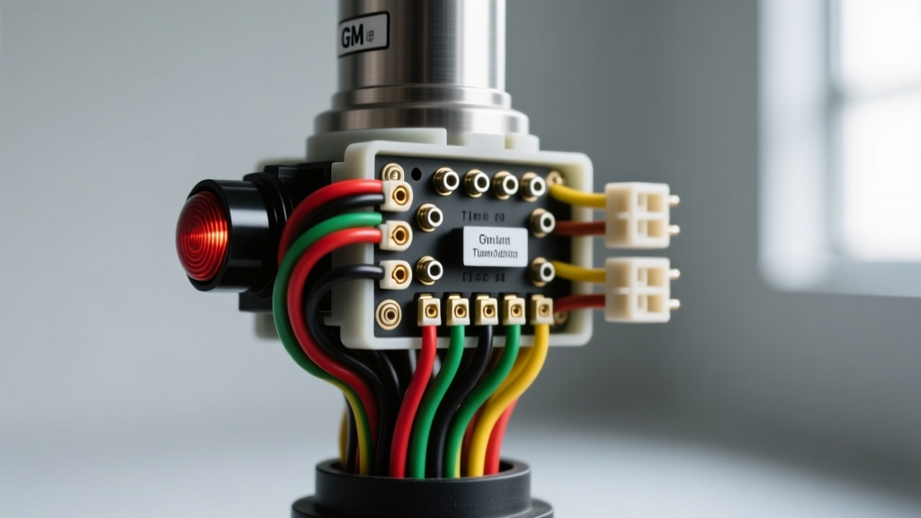
Overview of GM Steering Column Electrical Architecture
When referencing a wiring diagram for GM steering column assemblies, technicians must navigate a dense network of safety-critical and convenience circuits. This technical specification reference focuses primarily on the widely serviced GMT800 and GMT900 platforms (1999-2013 Chevrolet Silverado, GMC Sierra, Tahoe, and Yukon). The steering column serves as the primary routing conduit for the Supplemental Inflatable Restraint (SIR) clock spring, the multifunction switch (MFS), the Brake Transmission Shift Interlock (BTSI) solenoid, and the column-shift PRNDL illumination circuits.
Unlike modern CAN-bus localized steering control modules, these legacy GM columns rely on hardwired analog circuits routed through Delphi Packard Metri-Pack 280 and 150 series connectors. Understanding the exact pinouts, wire color codes, and American Wire Gauge (AWG) specifications is critical for diagnosing parasitic draws, backfeed conditions, and open-circuit faults without damaging the Body Control Module (BCM).
CRITICAL SAFETY WARNING: SIR System Protocol
Before probing any steering column connector, the SIR (airbag) system must be disabled. The clock spring utilizes distinct Yellow connectors. Failure to isolate the SIR system can result in accidental deployment.
- Disconnect the negative battery cable and isolate the terminal.
- Wait a minimum of 60 seconds to allow the SDM (Sensing and Diagnostic Module) backup capacitors to discharge.
- Never apply 12V directly to the yellow SIR harness pins; use only a digital multimeter (DMM) with a minimum 10-megohm impedance for continuity testing.
Multifunction Switch (MFS) Connector Pinout Reference
The primary interface between the driver and the vehicle's exterior lighting and wiper systems is the Multifunction Switch. The column harness interfaces with the main chassis harness via a multi-cavity connector block typically located near the base of the tilt-steering mechanism. Below is the standard GMT800 MFS chassis-side pinout configuration. All signal wires utilize GXL cross-linked polyethylene insulation per SAE J1128 standards.
| Cavity | Wire Color | AWG | Circuit Function | Destination / Module |
|---|---|---|---|---|
| A1 | Light Blue | 18 | Left Turn Signal Output | BCM / Rear Junction Block |
| A2 | Dark Green | 18 | Right Turn Signal Output | BCM / Rear Junction Block |
| A3 | Brown | 16 | Hazard Switch Feed (12V+) | Hazard Flasher Module |
| A4 | Yellow | 18 | High Beam Headlamp Feed | Headlamp Switch / Relay |
| A5 | Tan | 18 | Headlamp Dimmer Output (Low Beam) | Headlamp Switch / Relay |
| B1 | Black | 14 | Main Column Ground (G203) | Left Kick Panel Ground Bus |
| B2 | Purple | 18 | Horn Relay Control (Ground Trigger) | Underhood Fuse Block |
| B3 | Gray | 20 | Instrument Panel Dimmer Rheostat | BCM / IP Cluster |
| C1 | Dark Green/White | 18 | Wiper Washer Pump Control | Wiper Motor Module |
| C2 | White | 18 | Brake Switch Input (for Cruise Release) | PCM / Cruise Control Module |
Brake Transmission Shift Interlock (BTSI) Solenoid
For column-shift applications, the BTSI solenoid prevents the driver from shifting out of PARK unless the brake pedal is depressed and the ignition is in the RUN position. The solenoid is housed within the column shroud near the shift lever pivot.
BTSI Pin Configuration
- Pin A (Pink or Pink/Black): 18 AWG. Switched 12V+ feed from the IGN1 fuse circuit. Hot only in RUN and START.
- Pin B (Light Green/Black): 18 AWG. Ground control path routed through the BCM. The BCM monitors the Brake Pedal Position (BPP) sensor and completes the ground path to energize the BTSI solenoid, retracting the locking pin.
Diagnostic Note: If the shift lever is physically stuck in PARK despite the brake being applied, verify the 10A IGN1 fuse. If voltage is present at Pin A, probe Pin B with a test light. If the test light does not illuminate upon brake application, suspect a faulty BPP sensor or a BCM ground-driver fault.
SIR Clock Spring Specifications
The clock spring maintains electrical continuity between the stationary column harness and the rotating steering wheel hub. It houses the squib circuits for the driver airbag, the horn ground trigger, and steering wheel control switches (if equipped).
| Connector Color | Cavity | Wire Color | AWG | Function |
|---|---|---|---|---|
| Yellow (2-Way) | 1 | Yellow | 20 | SIR High Control (from SDM) |
| Yellow (2-Way) | 2 | Yellow/Black Stripe | 20 | SIR Low Control (to SDM) |
| Black (Horn) | - | Black | 18 | Horn Switch Ground Return |
Installation Torque Specs: When reinstalling the steering wheel onto the splined shaft after clock spring service, the steering wheel retaining nut must be torqued to 30 lb-ft (40 Nm). The clock spring must be centered (typically 2.5 turns from lock-to-lock) prior to installation to prevent internal ribbon cable snapping during full steering articulation.
Common Failure Modes & Diagnostic Decision Tree
GM steering columns of this era are notorious for a specific, baffling symptom: Activating the turn signal causes the wipers to engage, or the hazard lights flash when the brake pedal is pressed. This is rarely a fault of the column wiring itself, but rather a backfeed condition caused by a compromised ground.
Troubleshooting Backfeed & Phantom Voltage
- Symptom: Left turn signal illuminates the right turn indicator dimly; wipers pulse when turn signal is engaged.
- Root Cause Analysis: The MFS relies on a shared ground circuit (Black, 14 AWG, Circuit 1350) that routes to Splice Pack SP205, located behind the left kick panel. When SP205 suffers galvanic corrosion, the MFS seeks an alternate ground path. Current backfeeds through the BCM's internal logic gates, exiting through the wiper control or opposite turn signal circuit.
- Step 1: Disconnect the MFS chassis connector. Measure resistance between Cavity B1 (Black wire) and a known good chassis ground. It should read less than 0.5 ohms.
- Step 2: If resistance is high (OL or > 2.0 ohms), remove the left kick panel trim and locate SP205 (a multi-wire block with a single black pigtail to the chassis).
- Step 3: Inspect SP205 for green/white copper oxide corrosion. Do not simply clean it; the internal brass crimp barrels are compromised. Cut out SP205 and solder/seal the wires using adhesive-lined heat shrink, or replace with a new OEM Delphi splice pack.
- Step 4: If SP205 tests perfectly, the internal contacts of the Multifunction Switch are suffering from dielectric grease breakdown and carbon tracking. Replace the MFS assembly.
Terminal Repair and Crimping Standards
When repairing damaged wires at the column base, technicians must adhere to OEM crimping standards to prevent terminal pull-out and voltage drop. The GM column harness primarily uses Delphi Metri-Pack 280 terminals for 14-18 AWG wires.
- Stripping Length: 4.0mm to 5.0mm. Do not nick the copper strands.
- Tooling: Use a ratcheting crimper calibrated for Metri-Pack 280 (e.g., Delphi 12094430 or equivalent). A proper crimp will yield a pull-out force exceeding 45 Newtons for 18 AWG wire.
- Sealing: If the repair is within 6 inches of an exterior bulkhead connector, a silicone cavity plug must be inserted into any unused connector cavities to prevent capillary action moisture ingress.
Authoritative References
For comprehensive vehicle-specific schematics and connector cavity maps, technicians should consult the Helm Incorporated GM Service Manuals or OEM dealer portals. Wire insulation and gauge specifications strictly follow SAE J1128 Low Tension Primary Cable Standards. For detailed terminal pull-out forces and connector mating specifications, refer to the Delphi Connection Systems Metri-Pack Handbook.