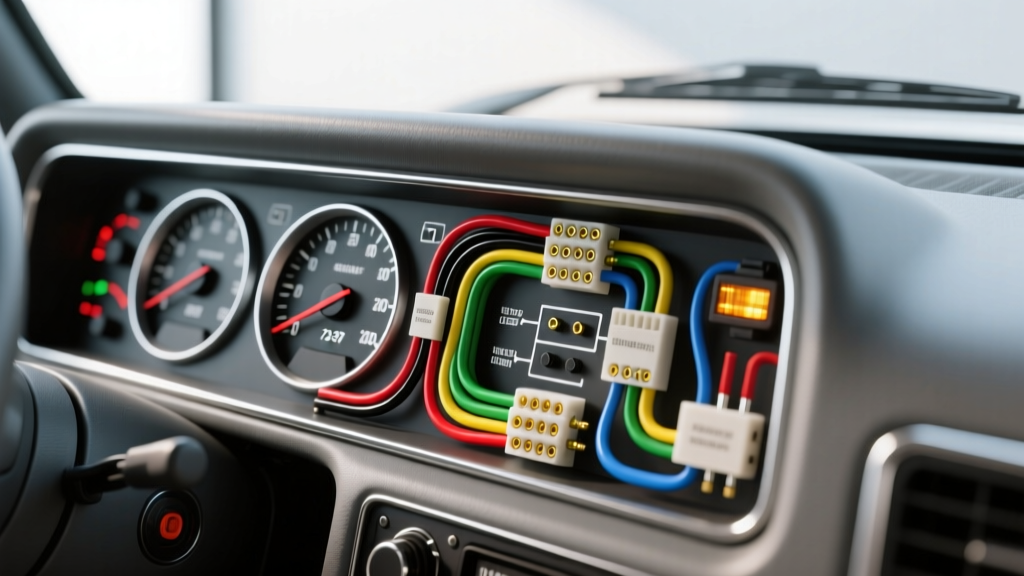
Understanding the 73-87 Chevy Truck Instrument Cluster Wiring Diagram
The 1973-1987 Chevrolet C/K "Square Body" trucks remain some of the most popular platforms for automotive restoration and modification. Whether you are restoring a 1978 Silverado or building a custom 1984 K10, understanding the 73 87 Chevy truck instrument cluster wiring diagram is critical. The electrical architecture of these trucks relies on a flexible Mylar printed circuit board (PCB) sandwiched behind the gauge housing, fed by a main multi-pin bulkhead connector. Over decades of heat cycling and vibration, these PCBs develop micro-fractures, and the OEM connectors suffer from terminal oxidation. This guide provides the exact OEM wire color codes, pinout configurations, and actionable upgrade paths for converting warning lamps to full sweep gauges or integrating modern stepper-motor displays.
OEM Cluster Bulkhead Connector Pinout and Wire Colors
The main harness connects to the cluster via a flat-blade GM connector. While the physical layout of the "Sweep" dash (1973-1980) differs from the "Straight" dash (1981-1987), the fundamental GM wire color codes remain remarkably consistent across the generation. When performing an upgrade, you must verify these circuits at the bulkhead connector before tapping into the harness.
| Circuit Function | OEM Wire Color | AWG Size | Notes / Upgrade Considerations |
|---|---|---|---|
| Ignition 12V Feed (Gauges) | Pink | 20 AWG | Switched 12V. Upgrade to 16 AWG if adding multiple high-draw digital displays. |
| Dash Illumination | Gray | 20 AWG | Variable voltage via headlight switch dimmer. Max 12V, dims to ~4V. |
| Main Ground | Black | 18 AWG | Notorious failure point. Always run a dedicated 14 AWG ground to the engine block. |
| Coolant Temp Sender | Dark Green | 20 AWG | Variable resistance. Do not confuse with Light Green (High Beam). |
| Fuel Level Sender | Tan | 20 AWG | 0-90 Ohm sweep. Requires clean ground at the tank sending unit. |
| Oil Pressure Sender (Gauge) | Light Blue | 20 AWG | Only present if truck originally had gauge cluster. See conversion section below. |
| Tachometer Signal | White | 20 AWG | 12V square wave from HEI distributor. Requires shielding from spark plug wires. |
| Left Turn Signal | Light Blue | 20 AWG | Flashes 12V. Ensure proper flasher relay amperage if using LEDs. |
| Right Turn Signal | Dark Green | 20 AWG | Flashes 12V. |
| High Beam Indicator | Light Green | 20 AWG | Grounds through the headlight dimmer switch on the floor/column. |
| Brake Warning Lamp | Pink/Black | 20 AWG | Grounds via proportioning valve switch during brake failure. |
The "Idiot Light" to Full Gauge Conversion Upgrade
Many base-model Square Body trucks were equipped with a warning lamp cluster (often called "idiot lights") instead of analog gauges. Upgrading to a full gauge cluster is a highly sought-after modification, but it requires more than just swapping the physical dash bezel. The OEM wiring harness on a warning-lamp truck lacks the variable-resistance sender wires and utilizes different sending units at the engine block.
Sourcing and Installing the Correct Sending Units
Warning lamp senders are simple normally-open switches that close (ground the circuit) when a threshold is crossed (e.g., 5 PSI for oil, 240°F for coolant). Full gauges require variable resistors. According to the Haynes Chevy Pick-ups 1973-1987 Repair Manual, the GM standard resistance values are:
- Fuel: 0 Ohms (Empty) to 90 Ohms (Full)
- Coolant Temp: ~185 Ohms (Cold) to ~65 Ohms (Hot)
- Oil Pressure: 0 Ohms (0 PSI) to 90 Ohms (60+ PSI)
When performing the swap, you must remove the 1-wire warning switches from the engine block and install the correct 1-wire variable senders. The thread pitch for the GM oil pressure sender is typically 1/8"-27 NPT, located near the distributor or above the oil filter adapter. Use Teflon tape sparingly, ensuring it does not cover the threads that make the electrical ground connection to the engine block.
Routing the New Sender Wires
If your chassis harness lacks the Dark Green (Temp) and Light Blue (Oil) wires, you will need to run new circuits. Use 20 AWG GXL (Cross-linked polyethylene) automotive wire, which meets SAE J1128 primary cable standards for under-hood temperature resistance. Route the wires through the firewall using an existing rubber grommet, keeping them at least 4 inches away from the HEI ignition coil and spark plug wires to prevent electromagnetic interference (EMI), which will cause erratic gauge sweeping.
Modernizing with Stepper Motor and Digital Gauges
For builders integrating modern digital clusters (like Dakota Digital VHX) or analog stepper-motor gauges (like AutoMeter), the OEM 73 87 Chevy truck instrument cluster wiring diagram serves as the foundation. These modern units feature solid-state microprocessors that read the OEM 0-90 Ohm fuel sender and 185-65 Ohm temp sender perfectly, eliminating the need for aftermarket sending units.
Power and Grounding Requirements for Digital Upgrades
Digital gauges are highly sensitive to voltage drops. The OEM Pink ignition wire and Black ground wire on a 40-year-old harness will often suffer from a 0.5V to 1.5V drop, causing digital displays to reset during engine cranking. To fix this:
- Run a dedicated 14 AWG power feed directly from a fused ignition source at the fuse block.
- Run a dedicated 14 AWG ground wire from the gauge harness directly to a clean, bare-metal point on the engine block or chassis.
- Use a digital multimeter to verify less than 0.1V of resistance between the gauge ground terminal and the battery negative post.
Troubleshooting the OEM Mylar PCB and HEI Tachometer Signal
Even if you retain the OEM analog gauges, the Square Body cluster has two notorious failure modes that mimic bad wiring or failed senders.
Mylar PCB Trace Fractures
The flexible copper traces laminated to the Mylar backing become brittle over time. A common symptom is the fuel gauge reading empty while the temp gauge pegs to hot, or all gauges dropping out when hitting a bump. Inspect the PCB by holding it up to a bright light; hairline cracks in the copper will be visible. Do not attempt to solder directly to the Mylar, as the heat will melt the substrate and lift the copper entirely. Instead, use 22 AWG stranded copper wire and conductive epoxy, or carefully scrape the Mylar coating back 1/4 inch on either side of the break, tin the exposed copper, and lay a jumper wire across the gap.
HEI Tachometer Signal Noise
The GM HEI distributor outputs a 12V square wave on the White tach wire. When upgrading to an aftermarket tachometer, you may notice the needle bouncing erratically at idle. This is caused by EMI or a weak pull-up signal. If your aftermarket tachometer reads zero or bounces, install a 10kΩ 1/2-watt pull-up resistor between the White tach wire and a clean 12V switched source. Additionally, ensure the White wire is routed using shielded cable, with the shield mesh grounded only at the dashboard end to prevent ground loops. For deeper wiring schematics and community-tested pinout variations, the 67-72chevytrucks.com Wiring Diagram Archives remain an invaluable resource for Square Body electrical anomalies.
Final Upgrade Verification Checklist
Before reassembling the dash bezel and tightening the cluster housing screws, perform a bench test with the cluster suspended. Turn the key to the "ON" position (do not crank). Verify that the fuel gauge reads the correct level, the choke light illuminates (if equipped), and the dash illumination dims smoothly when rotating the headlight switch. Torque the cluster housing retaining nuts to 15 in-lbs to prevent cracking the 40-year-old brittle plastic lens covers. By adhering to the OEM wire color codes and upgrading the power and ground feeds, your 1973-1987 Chevy truck will feature a reliable, modernized instrument cluster ready for the road.