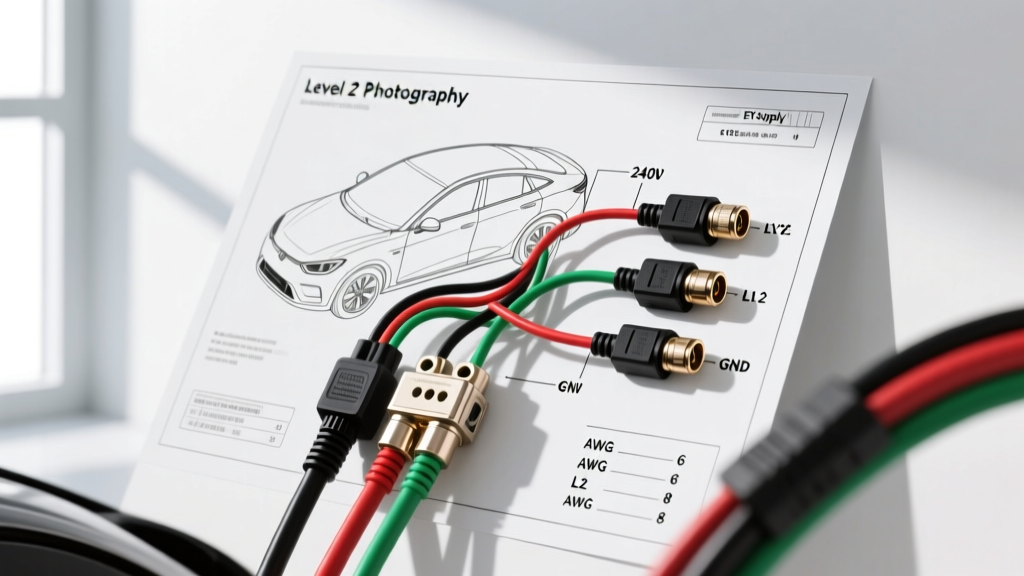
Understanding the 240V 3-Wire EVSE Supply Architecture
As electric vehicles (EVs) dominate modern automotive engineering, understanding the electrical infrastructure that powers them is critical for automotive electricians and advanced DIYers. When analyzing a 240v wiring diagram 3 wire configuration in an automotive context, we are specifically looking at the Electric Vehicle Supply Equipment (EVSE) circuit that feeds the vehicle's Onboard Charger (OBC). Unlike residential appliances that may require a neutral wire for 120V auxiliary components, a dedicated Level 2 EV charging circuit operates purely on 240V AC. Therefore, the National Electrical Code (NEC) Article 625 permits and encourages a 3-wire setup: Line 1 (L1), Line 2 (L2), and an Equipment Grounding Conductor (EGC). The neutral is entirely omitted, reducing conductor count and minimizing voltage drop over long conduit runs.
This complete wiring diagram walkthrough bridges the gap between the facility's electrical panel and the vehicle's high-voltage traction battery, detailing the exact wire gauges, pin configurations, and communication protocols required for safe, high-amperage charging.
Complete 240V 3-Wire Wiring Diagram Walkthrough
A standard 50-amp Level 2 charging circuit (delivering 40 amps of continuous charge current to the vehicle) requires precise execution. Below is the step-by-step schematic flow from the main breaker panel to the vehicle's charge port inlet.
1. Breaker Panel to EVSE Disconnect
The circuit originates at a 2-pole, 50-amp breaker in the main service panel. The two hot bus bars provide the split-phase 240V.
- L1 (Black): Routed from the breaker's top terminal.
- L2 (Red): Routed from the breaker's bottom terminal.
- EGC (Green/Bare Copper): Terminated at the panel's dedicated ground bus bar. Note: Never bond the neutral and ground bus bars on a subpanel feeding an EVSE.
2. The NEMA 14-50 Receptacle Termination
For a 3-wire 240V EV setup, the NEMA 14-50R receptacle is wired with L1, L2, and Ground. The neutral slot (W) on the 14-50R is left completely empty. Expert Warning: Automotive electrical failures often stem from thermal runaway at the receptacle. Do not use standard residential-grade receptacles. Always specify an industrial-grade receptacle, such as the Hubbell 9450A, which features higher clamping force and superior thermal dissipation. Terminal torque must be set to exactly 75 in-lbs using a calibrated torque screwdriver to prevent micro-arcing and subsequent melting.
Wire Gauge (AWG) and Conductor Specifications
Selecting the correct American Wire Gauge (AWG) is non-negotiable for continuous loads. EV charging is classified as a continuous load (operating for 3+ hours), meaning the circuit must be derated to 125% of the maximum continuous current. A 40A continuous charge requires a 50A circuit.
| Parameter | 50A Circuit (40A Charge) | 60A Circuit (48A Charge) |
|---|---|---|
| Breaker Size | 50A 2-Pole | 60A 2-Pole |
| Wire Gauge (Copper) | 6 AWG THHN/THWN-2 | 4 AWG THHN/THWN-2 |
| Wire Colors | Black, Red, Green | Black, Red, Green |
| Max Voltage Drop (3%) | ~110 feet | ~140 feet |
| Terminal Torque | 75 in-lbs (Receptacle) | 45 in-lbs (Hardwire Lug) |
Vehicle-Side Integration: SAE J1772 and OBC Pinouts
Once the 240V 3-wire power reaches the EVSE enclosure, the EVSE's internal contactor closes, sending L1 and L2 down the charging cable to the vehicle. The automotive industry standard for this interface in North America is the SAE J1772 connector. To understand how the vehicle manages this power, we must look at the SAE J1772-2017 standard pinout.
| Pin | Function | Wire Color (Typical Harness) | Vehicle-Side Destination |
|---|---|---|---|
| 1 | AC Line 1 (L1) | Black | OBC AC Input Relay |
| 2 | AC Line 2 (L2) | Red | OBC AC Input Relay |
| 3 | Protective Earth (Ground) | Green/Yellow | Vehicle Chassis Ground |
| 4 | Proximity Pilot (PP) | Orange/White | Charge Port ECU / BMS |
| 5 | Control Pilot (CP) | Purple/White | Charge Port ECU / BMS |
The Control Pilot (CP) PWM Handshake
The 240V AC does not simply flow into the vehicle upon plugging in. The EVSE and the vehicle's Battery Management System (BMS) must perform a digital handshake via the Control Pilot (Pin 5). The EVSE generates a 1kHz, ±12V square wave Pulse Width Modulation (PWM) signal. The duty cycle of this PWM signal dictates the maximum allowable current the vehicle's Onboard Charger (OBC) is permitted to draw. For a 40A continuous charge on our 50A 3-wire circuit, the EVSE outputs a 66.7% duty cycle. When the vehicle's BMS verifies the ground integrity and the Proximity Pilot (Pin 4) confirms the connector is fully seated, the vehicle closes its internal AC contactors, allowing the 240V L1 and L2 to enter the OBC.
Inside the Onboard Charger (OBC)
The vehicle's OBC is a highly complex power electronics module. It receives the 240V AC single-phase power and routes it through an Active Power Factor Correction (PFC) stage, followed by an isolated LLC resonant DC-DC converter. This circuitry rectifies and steps up the 240V AC into the 400V to 800V DC required to charge the high-voltage traction battery pack. The 3-wire ground (EGC) is continuously monitored by the vehicle's Ground Fault Interrupter (GFI) circuit; if a leakage current exceeding 5mA is detected between the AC lines and the chassis ground, the vehicle instantly opens the AC contactors and halts the charge.
Troubleshooting Common 240V EV Charging Faults
When diagnosing Level 2 charging failures, automotive technicians must evaluate both the facility's 3-wire supply and the vehicle's internal wiring harness. Use this diagnostic decision tree for common faults:
- Symptom: EVSE clicks, but vehicle displays 'Check Charge System' or refuses to charge.
Cause: Voltage drop or open ground.
Fix: Measure voltage between L1 and Ground, and L2 and Ground at the receptacle under load. Both should read ~120V. If L1-to-Ground reads 0V, the EGC is broken or the receptacle ground screw is loose. The vehicle's BMS will inhibit charging if ground continuity fails. - Symptom: NEMA 14-50 receptacle face is melted or discolored.
Cause: Thermal runaway due to improper torque or residential-grade hardware.
Fix: Replace the receptacle with an industrial Hubbell 9450A. Cut back any heat-damaged wire insulation, strip fresh copper, and torque terminals to exactly 75 in-lbs. Verify the breaker is not showing thermal discoloration. - Symptom: Charging initiates but aborts randomly after 10-20 minutes.
Cause: Control Pilot (CP) signal degradation or OBC thermal throttling.
Fix: Back-probe Pin 5 on the J1772 inlet while connected. Use an oscilloscope to verify the 1kHz PWM signal remains a clean square wave. If the signal degrades or drops below +9V on the positive pulse, inspect the CP wire for chafing inside the vehicle's charge port harness. If the signal is perfect, scan the OBC module for internal IGBT thermal fault codes.
Authoritative References & Standards
For further engineering specifications, always consult the primary governing bodies for automotive electrical systems and facility wiring: