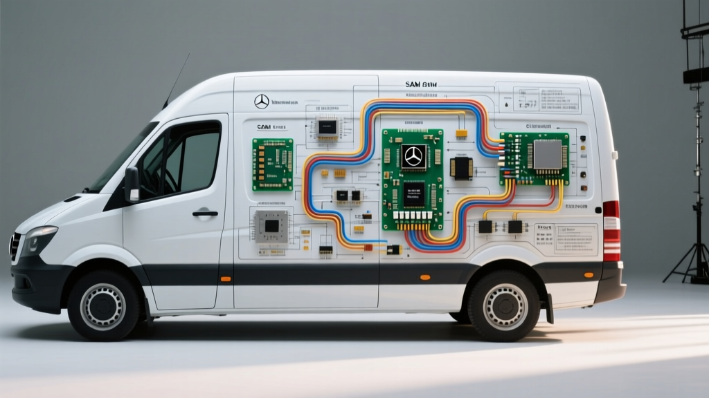
The Anatomy of a Mercedes Sprinter Wiring Diagram PDF
When troubleshooting the electrical architecture of a Mercedes-Benz Sprinter (whether the NCV3 906 chassis or the newer VS30 907 chassis), standard automotive diagnostic logic often falls short. The Sprinter relies on a highly multiplexed, module-dense network governed by strict Mercedes-Benz Workshop Information System (WIS) standards. Downloading a Mercedes Sprinter wiring diagram PDF is only the first step; interpreting the schematic nomenclature is where the real diagnostic battle is won or lost.
Unlike generic aftermarket diagrams, the OEM Sprinter PDF schematics utilize a strict alphanumeric grid system. Letters (A-Z) run horizontally across the top, while numbers (1-100) run vertically down the sides. This allows technicians to pinpoint exact wire routing paths across multi-page PDF documents. Furthermore, Mercedes-Benz uses a standardized component prefix code. For example, 'N' designates a control module (e.g., N10/1 for the Front SAM), 'M' designates a motor, 'R' is a resistor, 'X' is a connector, and 'Z' represents a splice or ground node.
Front SAM (N10/1) Pinout and Power Distribution
The Front Signal Acquisition Module (SAM), designated as N10/1 in the wiring diagram PDF, is the central nervous system for the Sprinter's engine bay and primary power distribution. It houses relays, fuses, and the terminating resistors for the powertrain CAN bus. A common failure mode in both the 906 and 907 chassis is parasitic draw caused by moisture intrusion into the SAM's lower connector housings, preventing the modules from entering 'sleep' mode.
Below is a critical reference table for the primary power and CAN-bus pins on the Front SAM. When testing these circuits, always use a high-impedance digital multimeter (DMM) and avoid piercing the wire insulation, which leads to capillary corrosion.
| Pin / Stud | Terminal / Signal | Wire Color (OEM) | AWG / mm² | Function & Diagnostic Notes |
|---|---|---|---|---|
| Stud M8 | Terminal 30 (B+) | Red (RD) | 4 AWG / 25mm² | Main Battery Feed. Torque spec: 15 Nm. Check for voltage drop under cranking load. |
| Pin 12 | CAN-H (Powertrain) | Green/White (GN/WH) | 20 AWG / 0.5mm² | CAN-C High. Dominant voltage ~2.6V. Terminating resistor located inside SAM. |
| Pin 13 | CAN-L (Powertrain) | Green/Brown (GN/BN) | 20 AWG / 0.5mm² | CAN-C Low. Recessive voltage ~2.4V. Must be twisted with CAN-H (1 twist per inch). |
| Pin 45 | Ground (W15/4) | Brown (BN) | 14 AWG / 2.5mm² | Logic Ground. High resistance here causes erratic injector pulse width signals. |
| Pin 88 | Terminal 15 (Ignition) | Black/Red (BK/RD) | 16 AWG / 1.5mm² | Ignition ON signal routed from the EZS via CAN-B, then hardwired to ECM. |
CAN Bus Topology and SAE J1939 Integration
The Sprinter's wiring diagram PDF will reveal multiple CAN networks. The most critical for drivability is the CAN-C (Powertrain) bus, which operates at 500 kbps. In heavy-duty and commercial Sprinter applications, this network often bridges to the SAE J1939 standard for PTO (Power Take-Off) and aftermarket upfitter integrations.
When reading the PDF schematic, look for the 120-ohm terminating resistors. In the Sprinter architecture, these are typically embedded inside the Engine Control Module (N3/10) and the Front SAM (N10/1). If your DMM reads 120 ohms across Pins 6 and 14 of the OBD-II port, you have an open circuit on one side of the bus. If you read 40 ohms, a third, unauthorized terminating resistor has been improperly spliced into the harness—a frequent issue in poorly executed RV or ambulance upfits.
CAN Bus Breakpoint Diagnostics
Instead of back-probing, which can spread the female terminal pins inside the MQS (Micro Quadlok System) connectors, use the PDF to locate designated 'X' breakout connectors. For example, X18/3 in the engine harness often serves as a diagnostic breakpoint. Disconnecting X18/3 allows you to isolate the engine harness from the chassis harness to determine which side of the circuit is dragging down the CAN voltage.
Decoding the EZS (Electronic Ignition Switch) Schematics
The EZS (N73) is the master gateway for the immobilizer and vehicle wake-up logic. In the wiring diagram PDF, you will notice that the EZS does not simply pass high current to the starter relay. Instead, it reads the transponder chip in the key, validates it with the ECU via CAN-B (Interior/Comfort bus), and then sends a digital 'Terminal 50' (Start Request) message over the network.
Common EZS Failure Mode: The solder joints on the EZS internal voltage regulator degrade due to thermal cycling. The PDF will show Terminal 30 (Constant Battery) and Terminal 30a (Secondary Battery) feeding the module. If the EZS loses power momentarily, it drops the CAN-B network, resulting in a 'Start Error' message on the dash and a disabled steering column lock (ESL). Always verify that the 15-amp mini-fuse feeding the EZS in the dashboard fuse block (F1) has clean, un-oxidated blades.
Grounding Architecture (W-Nodes) and Splice Packs (Z-Nodes)
Mercedes-Benz schematics dedicate specific pages to ground locations (W-nodes) and splice packs (Z-nodes). A profound mistake technicians make is assuming a ground is good simply because it shows continuity to the battery negative post. The Sprinter utilizes pulse-width modulated (PWM) grounds for components like the electric auxiliary water pump and the glow plug output stage.
Ground Verification Protocol
- Locate the W-Node: Use the component location PDF to find the exact ground stud (e.g., W11/4 located behind the right headlight assembly).
- Visual Inspection: Remove the M6 or M8 ground nut. Inspect for galvanic corrosion between the copper ring terminal and the aluminum chassis tab.
- Load Testing: Connect a headlight bulb (drawing ~5 Amps) between the B+ post and the ground ring terminal. A voltage drop greater than 0.1V under load indicates a high-resistance fault that will trigger false 'Short to Ground' codes in the SAM.
- Reassembly: Clean with a brass wire brush, apply dielectric grease to the *outside* of the connection (never between the mating surfaces), and torque the M6 nut to exactly 6 Nm.
Navigating the 'Wiring Diagram to Harness' Disconnect
One of the most frustrating aspects of using a Mercedes Sprinter wiring diagram PDF is dealing with mid-harness splices that are not explicitly detailed in the connector views. Mercedes utilizes ultrasonic welding and adhesive-lined heat shrink for Z-node splices deep inside the engine harness. If the PDF shows a wire changing color (e.g., from Black/Red to Black/Yellow) but no 'X' connector is listed, you are looking at a Z-node splice.
For advanced troubleshooting, always cross-reference the 'Current Flow' schematic with the 'Connector View' PDF. The connector views will provide the exact cavity pinout and terminal type (usually TE Connectivity MCP 1.2 or 2.8 series). When repairing a broken wire in a Sprinter harness, never use solder and electrical tape. The OEM standard requires crimping with a ratcheting terminal tool and sealing with dual-wall polyolefin heat shrink to maintain the harness's IP67 waterproof rating.
Summary of Best Practices for Sprinter Schematics
Mastering the Mercedes Sprinter wiring diagram PDF requires shifting from a 'power-and-ground' mindset to a 'network-and-module' mindset. By understanding the WIS grid system, respecting the CAN-bus terminating resistors, and adhering to strict torque and crimping specifications, you can accurately diagnose the most elusive electrical faults in the NCV3 and VS30 platforms. For ongoing community-driven technical bulletins and real-world harness routing photos, the Sprinter Source Technical Archives remain an invaluable supplementary resource to the OEM PDF documentation.