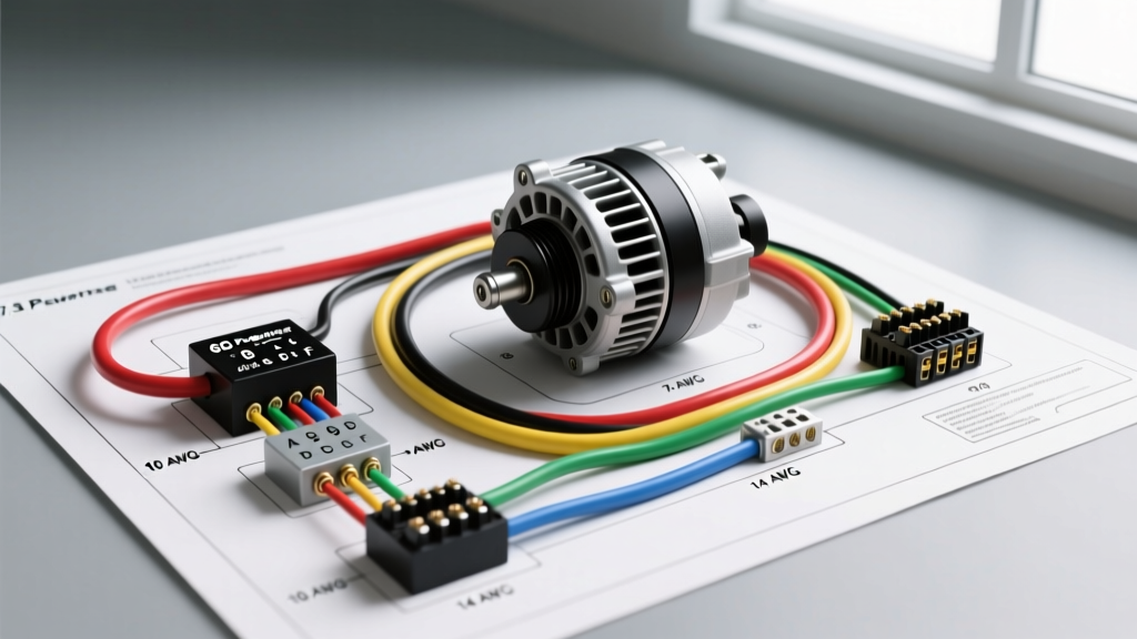
Introduction to the 7.3L Powerstroke Charging System
The 7.3L Powerstroke diesel engine, particularly in the 1999-2003 Ford Super Duty and E-Series vans, relies on a highly robust electrical system to maintain operation. Unlike modern common-rail diesels, the 7.3L utilizes a HEUI (Hydraulic Electric Unit Injector) system. The Injector Driver Module (IDM) requires a stable, high-amperage 12V input to step up voltage to approximately 115V for firing the injector solenoids. If the alternator wiring suffers from voltage drop or faulty sense circuits, the IDM will misfire, resulting in rough idle, stalling, or a dead pedal. Understanding the complete 7.3 Powerstroke alternator wiring diagram is essential for diagnosing parasitic draws, undercharging conditions, and Instrument Panel Cluster (IPC) warning light faults.
The Ford 6G Alternator Architecture
The 7.3L Powerstroke is equipped from the factory with a Motorcraft 6G series alternator, typically rated at 110 amps (Motorcraft GL-8516) or 130 amps (GL-8524) for heavy-duty applications. The 6G unit features an internal voltage regulator that is monitored by the Powertrain Control Module (PCM). The regulator relies on a 3-pin oval connector to manage battery sensing, dash indication, and PCM communication. Tracing these circuits from the alternator pigtail to the under-hood power distribution box and the PCM is the core of this wiring diagram walkthrough.
Complete 7.3 Powerstroke Alternator Wiring Diagram Walkthrough
To accurately diagnose charging system faults, we must break down the 3-pin oval connector (commonly replaced using Motorcraft pigtail WPT-1239 or WPT-1246) and the main output post. Below is the circuit-by-circuit analysis of the OEM wiring schematic.
Pin 1: Battery Sense Circuit (S Terminal)
The Sense wire is arguably the most critical circuit in the 7.3L charging diagram. It provides the internal voltage regulator with a real-time reading of the actual voltage reaching the vehicle's main power buses.
- OEM Wire Color: Yellow with Light Green tracer (Y/LG)
- AWG Size: 10 AWG or 12 AWG (fused inline)
- Routing: This wire routes from the alternator connector, through an inline 15A fuse, and splices directly into the starter motor relay battery positive terminal or the main power distribution box.
- Expert Insight: If this 15A inline fuse blows, the alternator will default to a base internal voltage (usually around 13.0V) and will not ramp up to the 14.2V - 14.5V required to properly charge the batteries and run the HEUI IDM under load.
Pin 2: Indicator / Excitation Circuit (I Terminal)
The Indicator circuit serves a dual purpose: it provides the initial excitation current to the alternator's rotor field upon key-on, and it grounds the dashboard charge indicator lamp.
- OEM Wire Color: Orange with Light Blue tracer (O/LB)
- AWG Size: 16 AWG
- Routing: Routes from the alternator regulator to the Instrument Panel Cluster (IPC) charge warning bulb, and then to the ignition switch (key-on 12V source).
- Expert Insight: If the dashboard charge bulb burns out, the circuit is broken. Without the initial excitation current passing through the bulb filament, the 6G alternator will not "turn on" or begin generating amperage until the engine is revved significantly to trigger residual magnetism.
Pin 3: PCM / IPC Communication Circuit (L Terminal)
The Logic or Communication wire allows the PCM to monitor the health of the charging system for load-shedding protocols and diagnostic trouble codes (DTCs).
- OEM Wire Color: White (W) or Light Green/Yellow (LG/Y) depending on chassis
- AWG Size: 16 AWG
- Routing: Connects to PCM Pin 2 (on early 99-01 models) or specific IPC logic gates to monitor frequency and voltage state.
- Expert Insight: A short to ground on this white wire will often trigger a false "Check Charging System" message on the digital overhead console, even if the alternator is outputting a perfect 14.4V.
Main Output and Grounding Specifications
The main charge cable connects to the threaded output post on the rear of the 6G alternator.
- Output Wire: 4 AWG or 6 AWG heavy-gauge stranded copper.
- Protection: Protected by a 175A Mega Fuse located in the under-hood Power Distribution Box (PDB).
- Hardware: Secured with a 10mm flange nut. Torque specification is 10-12 Nm (89-106 lb-in). Over-torquing can crack the internal rectifier bridge.
- Grounding: The alternator case grounds through the mounting brackets to the engine block. A dedicated 2 AWG braided ground strap must connect the engine block to the chassis frame to handle the massive return current required by the starter and dual 780 CCA batteries.
OEM Wiring Reference Table
| Circuit Function | Pin ID | OEM Wire Color | AWG Size | Destination / Component |
|---|---|---|---|---|
| Battery Sense | S | Yellow / Light Green | 10-12 AWG | Starter Relay / PDB (via 15A Fuse) |
| Indicator / Excitation | I | Orange / Light Blue | 16 AWG | IPC Charge Lamp / Ignition Switch |
| PCM Logic / Status | L | White | 16 AWG | PCM / Overhead Console |
| Main Output | B+ | Black / Red (Heavy) | 4-6 AWG | PDB Mega Fuse (175A) / Battery Pos |
Dual Alternator Configurations (Ambulance & Snowplow Prep)
Many 7.3L Powerstroke chassis (especially E-350 cutaways and F-350 DRW ambulances) were equipped with a dual alternator setup from the factory. In this wiring diagram variation, the upper and lower alternators are wired in parallel but utilize an isolated sense circuit. The primary alternator senses the house battery bank, while the secondary alternator senses the chassis battery. When diagnosing dual 6G systems, always verify that the 12 AWG sense wires have not been spliced together by a previous owner, as this causes the alternators to "fight" each other, leading to premature voltage regulator failure.
Diagnostic Decision Tree for 7.3L Charging Faults
Use this symptom-cause-fix sequence to troubleshoot the 7.3 Powerstroke alternator wiring diagram in the field:
- Symptom: Batteries read 12.1V at rest, but drop to 11.5V while idling. Dash charge light is OFF.
- Cause: Blown 15A inline fuse on the Yellow/Light Green sense wire, or high resistance on the main 4 AWG output cable.
- Fix: Perform a voltage drop test across the 175A Mega Fuse and the main charge cable. Replace the sense fuse if B+ is missing at the S pin.
- Symptom: Alternator whines, output exceeds 15.5V, boiling the batteries.
- Cause: Open circuit on the S (Sense) wire or bad ground at the alternator case.
- Fix: The regulator has lost its reference voltage and is maxing out the field coil. Clean alternator mounting ears and verify continuity of the Y/LG wire to the battery positive.
- Symptom: Dash charge light illuminates, but multimeter shows 14.2V at the battery.
- Cause: Short to ground on the White (L) PCM wire or failing IPC bulb socket.
- Fix: Unplug the 3-pin alternator connector. If the light stays on with the key on, the fault is in the chassis harness or PCM, not the alternator.
Authoritative References & Standards
For further diagnostic procedures and standardized testing protocols, refer to the following automotive electrical resources:
- SAE International - Refer to SAE J1171 and SAE J1113 for standards regarding automotive electrical component testing, voltage drop thresholds, and AWG current-carrying capacities in high-heat engine bay environments.
- Motorcraft Service Parts - Official OEM specifications for the 6G alternator series, WPT-1239 pigtails, and Mega Fuse ratings for Ford Super Duty applications.
- Haynes Manuals - Comprehensive chassis-specific wiring schematics and PCM pinout reference charts for 1999-2003 Ford 7.3L Powerstroke diesel platforms.