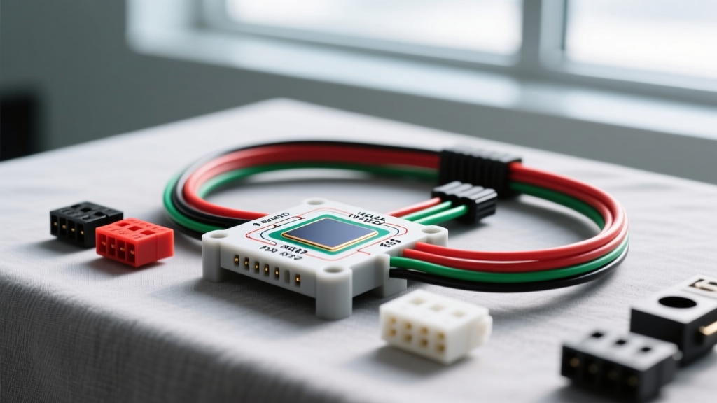
Introduction to the 454b Sensor (4-Wire HO2S)
When DIY mechanics and professional technicians search for a 454b sensor wiring diagram, they are typically referencing the universal 4-wire Heated Oxygen Sensor (HO2S) circuits commonly found in GM/Chevy V8 applications (including the legendary 454 Big Block Vortec engines) and their corresponding aftermarket pigtail connectors. Understanding this specific 4-wire configuration is a fundamental rite of passage for anyone working on OBD-II era engine management systems.
The oxygen sensor is the cornerstone of your vehicle's closed-loop fuel control. A failing sensor or a botched wiring repair can lead to rich/lean codes (P0171, P0172), poor fuel economy, and catalytic converter damage. This beginner-friendly guide will demystify the 454b sensor wiring diagram, breaking down the pinouts, wire gauges, and proper splicing techniques required for a permanent, factory-quality repair.
Understanding the 4-Wire Oxygen Sensor Circuit
To read a 454b sensor wiring diagram effectively, you must first understand that a 4-wire HO2S actually contains two completely separate circuits housed within a single stainless steel shell. Treating them as one circuit is the most common beginner mistake.
1. The Sensing Element (Signal Circuit)
The core of the sensor is a Zirconia dioxide element that generates a voltage based on the difference in oxygen content between the exhaust gas and the outside atmosphere. This circuit operates on extremely low current and requires high-impedance wiring to prevent signal degradation. It consists of a Signal wire and a dedicated Signal Ground wire.
2. The Ceramic Heater (Heater Circuit)
Zirconia sensors only become active and begin generating accurate voltage signals when they reach approximately 600°F (315°C). To achieve this quickly upon cold startup (and to meet OBD-II readiness monitor requirements), the sensor includes an internal ceramic heating element. This circuit draws significantly more current and requires thicker wiring. It consists of a 12V Heater Power wire and a Heater Ground wire.
454b Sensor Wiring Diagram & Pinout Table
Below is the standard pinout and wire color reference for a GM-style 4-wire HO2S (Metri-Pack 150 series connector), which is the most common application for the 454b pigtail reference. Note: Always verify with a factory service manual, as aftermarket sensor wire colors (like Bosch universal sensors) may differ from the vehicle's chassis harness.
| Pin | Function | Typical GM Harness Color | Wire Gauge (AWG) | Destination / Notes |
|---|---|---|---|---|
| A | Heater 12V Power | Pink or Pink/Black | 14 AWG | Fused ignition source (PCM controlled relay) |
| B | Heater Ground | Black/White | 14 AWG | PCM internal driver or chassis ground |
| C | Signal Output | Purple | 18 or 20 AWG | Direct to PCM (High impedance input) |
| D | Signal Ground | Purple/White or Tan | 18 or 20 AWG | PCM dedicated sensor ground (Do NOT chassis ground) |
Step-by-Step Wiring & Splicing Fundamentals
The exhaust environment is brutal. Temperatures routinely exceed 800°F, and the undercarriage is exposed to water, salt, and road debris. Using T-taps, scotch locks, or standard electrical tape will guarantee a failed repair within weeks. Follow these professional steps when executing your 454b sensor wiring diagram repair.
Tools and Materials Required
- Wire Strippers: Precision strippers for 14 AWG and 18 AWG wires.
- Solder: Rosin-core electrical solder (NEVER use acid-core plumbing solder).
- Heat Shrink: Marine-grade, adhesive-lined polyolefin heat shrink (3:1 shrink ratio).
- Heat Source: Heat gun (avoid open-flame torches near fuel lines).
- Multimeter: For continuity and voltage verification.
The Proper Solder-and-Shrink Method
- Prep the Wires: Cut the damaged section out. Strip exactly 1/2 inch of insulation from both the harness side and the pigtail side.
- Slide on Heat Shrink: Cut a piece of adhesive-lined heat shrink about 1.5 inches long and slide it onto the wire before making the connection.
- The Western Union Splice: Cross the stripped wires in an 'X' shape, twist them together tightly, and wrap the ends around the main wire. This provides mechanical strength before the solder even melts.
- Solder the Joint: Heat the wire (not the solder) with your iron, then apply the rosin-core solder until it wicks completely into the copper strands. The joint should look shiny and smooth, not dull and clumpy.
- Seal the Connection: Slide the adhesive-lined heat shrink over the soldered joint. Apply heat evenly from the center outward until the adhesive oozes slightly from both ends, creating a waterproof seal.
Common Troubleshooting & Multimeter Testing
If you have followed the 454b sensor wiring diagram but are still experiencing OBD-II codes, you must isolate whether the failure is in the wiring harness or the sensor itself.
Testing the Heater Circuit (Pins A & B)
The heater circuit is the most common point of failure. A burnt-out heater will trigger codes like P0135 or P0155.
- Resistance Test (Sensor Side): Set your multimeter to Ohms (Ω). Probe the two heater pins on the sensor itself. A healthy Zirconia sensor heater should read between 4.0 and 12.0 ohms at room temperature. If it reads 'OL' (Open Line), the internal heater is broken, and the sensor must be replaced.
- Voltage Test (Harness Side): Turn the ignition to the 'ON' position (engine off). Probe the harness connector. You should see 12V (battery voltage) on the power wire. If you have 0V, check the O2 sensor fuse in the underhood fuse block.
Testing the Signal Circuit (Pins C & D)
The signal circuit requires the engine to be running and fully warmed up (closed-loop operation).
- DC Voltage Test: Set your multimeter to DC Volts. Back-probe the Signal wire (Pin C) while the engine is idling. A properly functioning narrowband sensor should rapidly toggle between 0.100V (Lean) and 0.900V (Rich) roughly once per second (1Hz).
- Lazy Sensor Diagnosis: If the voltage slowly drifts or stays stuck at 0.45V, the sensor may be contaminated by oil ash or coolant silicates, or the Signal Ground (Pin D) may have excessive resistance. Never ground the signal wire to the chassis; it must return to the PCM to avoid ground loop interference.
Advanced Diagnostics: Oscilloscope vs. Multimeter
While a digital multimeter (DMM) is great for basic checks, its internal sampling rate is often too slow to capture the rapid switching of an oxygen sensor. For true diagnostic depth, automotive professionals use a digital storage oscilloscope (DSO). According to the Pico Technology Automotive Waveform Library, a healthy HO2S waveform should display sharp, square-ish transitions between rich and lean thresholds, with clean, flat tops and bottoms. If the waveform shows rounded edges or excessive noise, it indicates high resistance in the 454b sensor wiring diagram circuit, usually caused by corroded Metri-Pack terminals or a failing PCM driver.
Authoritative Resources & Further Reading
Proper electrical repairs require adherence to industry standards. For deeper dives into OBD-II protocols and oxygen sensor theory, consult the following authoritative resources:
- SAE International: Review the SAE J1979 Standard for comprehensive definitions of OBD-II diagnostic trouble codes and readiness monitor requirements related to HO2S circuits.
- AA1Car Automotive Library: The AA1Car Oxygen Sensor Technical Guide provides excellent visual breakdowns of Zirconia vs. Titania sensor operation and common contamination failure modes.
Final Thoughts on the 454b Wiring Repair
Tackling a 454b sensor wiring diagram doesn't require an engineering degree, but it does demand respect for the specific requirements of the signal and heater circuits. By using the correct AWG wire, executing proper solder-and-shrink splices, and verifying your work with a multimeter, you can restore your vehicle's fuel trim to factory specifications and ensure your catalytic converter survives for the long haul. Always prioritize the dedicated PCM signal ground over a convenient chassis ground, and your OBD-II system will reward you with a clean bill of health.