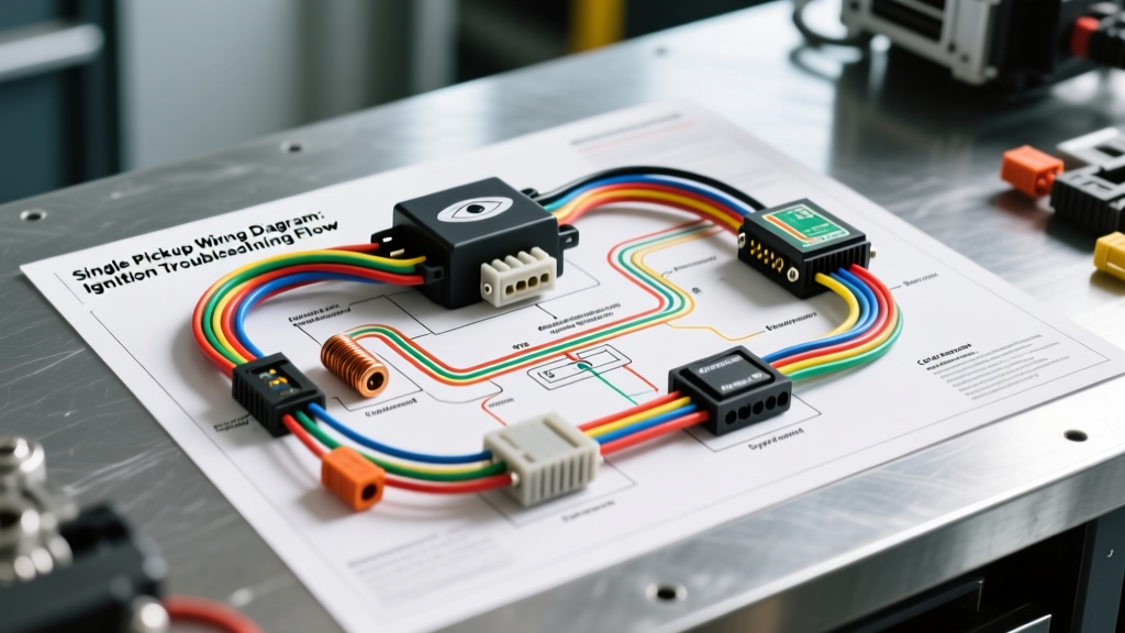
Terminology Note: While 'pickup' is colloquially used to describe light-duty trucks, in advanced automotive electrical diagnostics and motorsport wiring, a 'single pickup' refers to the single-coil Variable Reluctance (VR) magnetic pickup sensor. This component is the backbone of ignition triggers, HEI conversions, and EFI timing references. This guide focuses exclusively on the single magnetic pickup wiring diagram and sensor circuit diagnostics.
Understanding the Single Pickup Ignition Circuit
The single magnetic pickup coil operates on Faraday's Law of Induction. As a ferrous reluctor wheel (trigger wheel) rotates past the sensor's magnetic core, the changing magnetic field induces an Alternating Current (AC) voltage signal. This raw AC signal is then sent to a Capacitive Discharge Ignition (CDI) module, an HEI control module, or an Engine Control Unit (ECU) to dictate spark timing. Because the single pickup wiring diagram relies on analog voltage generation rather than digital Hall-effect switching, it is highly susceptible to Electromagnetic Interference (EMI) and physical air-gap degradation. Troubleshooting this circuit requires a systematic, step-by-step flow to isolate mechanical, physical, and electrical faults.
Step 1: Visual Inspection & EMI Routing Audit
Before touching a multimeter, you must verify the physical integrity of the harness. Single pickup sensors generate a very low-voltage analog signal (often under 2 volts at cranking speeds). If the wiring harness is not properly shielded, Radio Frequency Interference (RFI) from spark plug wires or the alternator stator will induce 'noise' into the circuit, causing the CDI box to trigger multiple sparks or advance timing erratically.
Harness Verification Checklist
- Wire Gauge & Type: Verify the harness uses 18 AWG stranded copper. Per SAE International J1128 standards for low-tension primary cable, the wire must be rated for under-hood thermal cycling.
- Shielding: The two signal wires must be a Shielded Twisted Pair (STP). The metallic shield must be grounded at the CDI/Module end only to prevent ground loops.
- Routing Proximity: The pickup wires must be routed at least 4 inches away from high-voltage spark plug wires, ignition coils, and alternator output terminals.
- Connector Integrity: Inspect the Weather-Pack or Molex 2-pin connector for terminal oxidation or 'fretting' corrosion, which adds unwanted resistance to the circuit.
Step 2: Static Resistance Testing (The Coil)
The internal copper windings of the single pickup coil have a specific resistance range. If the resistance is too high, the coil is failing or has a broken internal strand. If the resistance is near zero, the internal windings have shorted.
- Disconnect the 2-pin sensor connector from the ignition module or CDI box.
- Set your Digital Multimeter (DMM) to the Ohms (Ω) setting, selecting the 2k range.
- Probe the two terminals on the sensor side of the connector (polarity does not matter for static resistance testing on a single pickup).
- Compare your reading to the manufacturer specifications below.
| Manufacturer / System | Target Resistance (Ω) | Wire Color Standard | Failure Threshold |
|---|---|---|---|
| MSD (Holley) Flying Magnet / Pro-Billet | 400Ω - 600Ω | Violet & Green | <300Ω or >800Ω |
| GM HEI (4-Pin Module Conversion) | 700Ω - 1,200Ω | White & Green (or Black/White) | <500Ω or Open (OL) |
| Holley Sniper EFI / Hyperspark | 350Ω - 550Ω | Violet & Green | >1kΩ |
| Accel / Mallory Points-to-Electronic | 500Ω - 900Ω | Red & Brown | Open Circuit |
Step 3: Dynamic AC Voltage Output Test (Cranking)
A common rookie mistake is testing a magnetic pickup coil with the DMM set to DC Volts. Because the sensor generates an alternating current as the North and South poles of the magnetic field collapse and expand, you must use the AC Voltage setting.
- Reconnect the sensor to the harness, but use a T-pin or back-probe to access the wire terminals without piercing the wire insulation (which invites corrosion).
- Set the DMM to AC Volts (V~).
- Crank the engine (do not start). You are looking for the minimum threshold voltage required to 'wake up' the CDI module.
- Most aftermarket CDI boxes require a minimum of 0.8V to 1.2V AC at cranking speeds (150-250 RPM) to trigger the spark.
- If the AC voltage is present but below 0.5V, the issue is rarely the electrical wiring; it is almost always a mechanical air-gap or reluctor metallurgy issue.
Step 4: Reluctor Air Gap & Metallurgy Verification
According to Delphi Technologies sensor diagnostic guidelines, the physical relationship between the single pickup core and the reluctor wheel dictates signal amplitude. The single pickup diagram does not account for mechanical wear, which is a leading cause of 'no-spark' conditions at high RPMs.
- The Air Gap: Use a brass feeler gauge (never steel, as it will pull on the magnet and give a false reading) to measure the gap between the sensor tip and the reluctor tooth. The ideal gap is 0.010 to 0.015 inches. A gap wider than 0.025 inches will cause the signal to drop below the module's trigger threshold at low cranking speeds.
- Reluctor Runout: Mount a dial indicator on the distributor shaft or crank trigger. If the reluctor wheel has more than 0.003 inches of lateral runout, the air gap will fluctuate wildly, causing erratic timing retardation at high RPM.
Step 5: Module Pinout & Bias Voltage Check
Some modern EFI systems and advanced CDI boxes apply a small DC 'bias' or 'pull-up' voltage to the single pickup circuit to monitor for open circuits. If you measure DC voltage on the sensor wires while disconnected, trace it back to the module. For example, in the Holley / MSD 6AL-2 wiring schematic, the Violet wire connects to Pin 1 (Magnetic Pickup Positive) and the Green wire connects to Pin 2 (Magnetic Pickup Negative). Reversing these wires will not damage the sensor, but it will invert the AC sine wave, potentially causing the module to trigger on the falling edge of the signal rather than the rising edge, resulting in erratic timing.
Troubleshooting Decision Tree: No-Spark / Misfire Diagnosis
Follow this logical flow when diagnosing a single pickup wiring diagram failure:
- Symptom: Engine cranks but has zero spark.
- Action: Test static resistance (Step 2).
- If Open (OL): Internal coil winding is broken. Replace sensor.
- If Resistance is Normal: Proceed to AC Voltage test (Step 3).
- Symptom: AC Voltage during crank is below 0.5V.
- Action: Inspect air gap (Step 4).
- If Gap is >0.020": Adjust sensor bracket or check distributor shaft bushing wear.
- If Gap is correct: Check reluctor wheel material. (Aluminum or non-magnetic stainless steel will not induce a magnetic field; it must be low-carbon steel).
- Symptom: Engine backfires through the carburetor/intake upon startup.
- Action: Verify wire polarity at the CDI module.
- Fix: Swap Violet and Green wires at the module connector to correct the sine wave edge triggering.
- Symptom: Timing advances/retards erratically above 4,000 RPM.
- Action: Audit EMI shielding (Step 1).
- Fix: Ensure shield drain wire is grounded only at the CDI box, not at the sensor. Replace unshielded wire with 18 AWG STP harness.
Summary of Best Practices
Mastering the single pickup wiring diagram requires looking beyond the copper and understanding the electromagnetic environment under the hood. Always use shielded twisted-pair wiring, adhere strictly to the manufacturer's resistance and air-gap specifications, and never attempt to diagnose an analog VR sensor using DC voltage metrics. By following this step-by-step troubleshooting flow, you can confidently isolate whether a misfire or no-start condition is rooted in the wiring harness, the sensor coil, or the mechanical reluctor assembly.