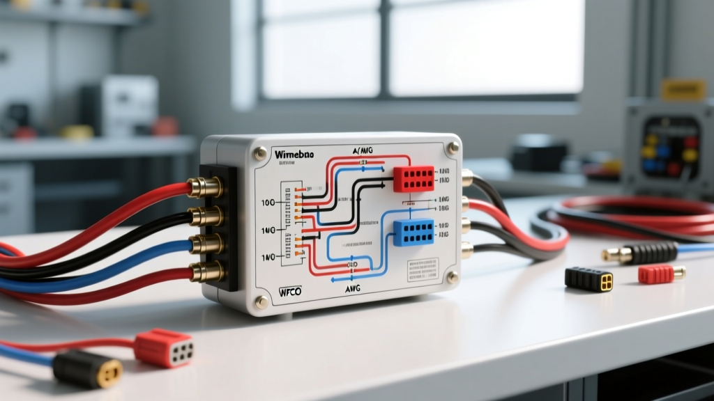
Winnebago House Power Conversion Architecture
Understanding the electrical architecture of a Winnebago motorhome requires distinguishing between the chassis electrical system (powered by the engine alternator) and the house electrical system (powered by shore power, generators, and the power converter). The power converter is the critical bridge in this ecosystem, stepping down 120V AC shore power to 12V DC to run house appliances, lighting, and water pumps while simultaneously maintaining the deep-cycle battery bank. Whether you are troubleshooting a legacy Parallax 7300 series unit in a 2005 Sightseer or mapping a modern WFCO WF-8955 or Progressive Dynamics PD4655 in a newer Minnie Winnie, accessing the correct Winnebago converter wiring diagram PDF is the first step in any diagnostic or upgrade procedure.
Sourcing the Official Winnebago Converter Wiring Diagram PDF
Winnebago provides model-specific wiring diagrams through their official owner portal. Unlike standard automotive schematics, RV diagrams are divided into chassis (Ford/Workhorse/Freightliner) and house (Winnebago-built) systems. To locate the exact Winnebago Official Wiring Diagram Portal document for your rig, you will need your specific 6-digit wiring diagram code (e.g., 152847 for a 2018 Minnie Winnie 22R). These PDFs detail the exact routing from the main AC distribution panel to the converter's AC input terminals, and the subsequent DC output routing to the main DC fuse block and battery isolation relay.
120V AC Input Wiring Specifications
The AC input side of the converter connects directly to a dedicated breaker on the main 120V AC load center. In most Winnebago Class A and Class C motorhomes equipped with 30-amp or 50-amp shore power services, the converter is fed by a 15A or 20A single-pole breaker.
AC Terminal Block Routing & Torque Specs
| Parameter | Specification | Notes |
|---|---|---|
| Input Voltage | 120V AC, 60Hz | Tolerance: 105V - 130V AC |
| Wire Gauge (AC) | 10 AWG Stranded Copper | THHN/THWN rated for 90°C |
| Wire Color Code | Black (Hot), White (Neutral), Green (Ground) | Do not swap Neutral and Ground at the converter |
| Terminal Torque | 14 in-lbs (1.58 Nm) | Over-torquing strips the brass terminal block |
| Breaker Rating | 15A or 20A (Max) | Depends on converter max AC draw (e.g., 900W max) |
Technical Note: When referencing the Winnebago converter wiring diagram PDF, pay close attention to the AC ground routing. The green ground wire must terminate on the converter's chassis ground lug and bond back to the main AC ground bus bar. A floating ground on the converter chassis will cause electromagnetic interference (EMI) and can trigger GFCI nuisance tripping on branch circuits, a known issue in older Winnebago Adventurer models.
12V DC Output & Battery Charging Circuit Specifications
The DC output side is where the majority of installation errors and voltage drop issues occur. The converter outputs a nominal 13.6V DC (in float mode) and must supply enough amperage to run the 12V house loads while charging the batteries. Modern Winnebago motorhomes typically use 45A, 55A, or 60A converters.
DC Output Routing & Fusing Requirements
| Parameter | Specification | Notes |
|---|---|---|
| Output Voltage | 13.2V - 14.4V DC | Varies by charging stage |
| Wire Gauge (DC) | 4 AWG or 2 AWG Stranded | Must meet SAE J1127 / ABYC E-11 standards for voltage drop |
| Wire Color Code | Red (B+), White (B- / DC Ground) | RVIA standard uses WHITE for 12V DC ground, not black |
| Main DC Fusing | 60A Class T or ANL Fuse | Must be installed within 7 inches of the battery positive post |
| Lug Torque (3/8") | 120 in-lbs (13.5 Nm) | Use dielectric grease on battery terminals |
Critical Warning: Automotive mechanics frequently make the mistake of using black wire for 12V DC ground. In Winnebago house wiring, black is often used for 12V switched hot (e.g., awning controls or slide-out motors), while white is the standardized 12V DC ground. Reversing these will instantly blow the converter's reverse polarity fuses and may destroy the internal MOSFETs.
Multi-Stage Charging Profiles (WFCO & Progressive Dynamics)
Modern Winnebago motorhomes utilize smart, multi-stage converters. When reviewing the technical specs in the Progressive Dynamics RV Converter Specifications or WFCO manuals, you will note four distinct charging phases designed to prolong the life of flooded lead-acid, AGM, or Gel batteries.
- Bulk Mode (14.4V DC): Triggered when battery voltage drops below 12.6V. The converter delivers maximum amperage (e.g., 55A) until the battery bank reaches 14.4V.
- Absorption Mode (13.6V DC): Voltage is held at 13.6V while amperage tapers off. This prevents gassing and overheating of the electrolyte.
- Float Mode (13.2V DC): The default resting state. Maintains the battery at 100% state of charge without overcharging or boiling off water.
- Equalization Mode (14.9V DC): Manually triggered (usually via a dip switch or button press) for 4-8 hours to desulfate flooded lead-acid battery plates. Never run equalization on AGM or Lithium batteries.
Diagnostic Troubleshooting & Real-World Failure Modes
When the Winnebago converter wiring diagram PDF confirms that all routing is correct, but the system is still failing, technicians must look at component-level failure modes. Below are the most common issues encountered in Winnebago service bays.
1. Blown Reverse Polarity Fuses
Located on the main DC distribution board (often adjacent to the converter), these are typically two 30A or 40A ATO blade fuses. If a user accidentally wires a new house battery backward, or if a 12V appliance shorts to ground, these fuses sacrifice themselves to save the converter's internal diodes. Fix: Test with a multimeter for continuity. If blown, trace the DC load center for a short before replacing.
2. Thermal Shutdown & Cooling Fan Failure
Converters like the WFCO 8900 series rely on a thermostatically controlled cooling fan. If the fan bearings seize due to dust ingestion (common in dry camping environments), the internal thermal cutoff switch will open at 165°F (74°C), halting all DC output. Diagnostic: Measure the 12V DC pins on the fan connector. If 12V is present but the fan is not spinning, replace the fan assembly. Do not bypass the thermal switch.
3. Electrolytic Capacitor Degradation (High Ripple Voltage)
Over 7-10 years, the internal electrolytic capacitors on the converter's DC filtering board dry out. This results in high AC ripple voltage superimposed on the DC output. Symptom: 12V LED lights will flicker, and audio systems will emit a high-pitched alternator-like whine. Diagnostic: Set your multimeter to AC Voltage. Measure across the DC output terminals. Any AC voltage reading above 0.5V AC indicates failed filter capacitors. The entire converter unit should be replaced, as component-level board repair is rarely cost-effective in an RV environment.
Upgrade Path: Parallax to Progressive Dynamics
Many older Winnebago models (2000-2010) shipped with Parallax 7345 or 7355 single-stage converters. These units are notorious for overcharging batteries during long-term storage. Upgrading to a Progressive Dynamics PD4645 or PD4655 is a direct physical swap in most Winnebago power centers. The AC and DC terminal block locations are standardized to SAE dimensions, meaning the existing 10 AWG AC and 4 AWG DC wiring can be reused, provided the wire insulation shows no signs of thermal cracking. Always verify the new unit's DIP switch settings match your specific battery chemistry (Flooded, AGM, or Gel) before applying shore power.