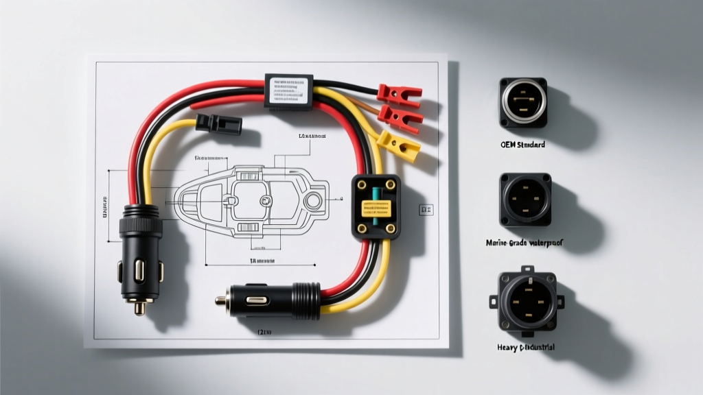
Understanding the 12V Accessory Power Outlet (APO)
While originally designed to heat a cigarette lighter coil, the modern 12V accessory power outlet (APO) is a critical power distribution node in any vehicle. Whether you are installing an aftermarket socket in a custom camper van, replacing a melted OEM unit in a daily driver, or upgrading a truck for heavy-duty inverters, understanding the correct wiring diagram for cigarette lighter plug circuits is essential for safety and reliability. Poorly executed 12V socket wiring is a leading cause of automotive electrical fires, primarily due to undersized wiring, improper fuse placement, and high-resistance ground connections.
This guide provides a comprehensive wiring schematic breakdown, followed by a product comparison of the most common 12V socket types on the market, ensuring you select the right hardware for your specific amperage requirements.
Universal Wiring Diagram for Cigarette Lighter Plug Circuits
Regardless of the socket brand or style, the fundamental electrical topology of a 12V cigarette lighter circuit remains constant. The circuit must always be protected by a fuse located as close to the power source (battery or distribution bus) as possible.
Circuit Schematic Topology
- Power Source: 12V Battery Positive Terminal or Ignition-Switched Fuse Block.
- Overcurrent Protection: Inline ATO/ATC Blade Fuse or Mini-Fuse (rated to wire capacity).
- Positive Feed: 14 AWG or 12 AWG primary wire routed to the socket.
- Socket Center Pin: Receives the positive feed (Bottom/Center Terminal).
- Load: The plugged-in accessory draws current.
- Socket Side Springs: Complete the circuit via the accessory's side contacts.
- Ground Return: Socket casing or dedicated ground terminal routed to vehicle chassis.
Standard Socket Pinout & Terminal Configuration
| Terminal Point | Polarity | Connection Type | Standard Wire Color (Aftermarket) |
|---|---|---|---|
| Center Contact Pin | Positive (+12V) | 6.3mm (1/4") Spade or Screw | Red (or Yellow for constant 12V) |
| Outer Casing / Side Springs | Negative (Ground) | 6.3mm Spade or Ring Terminal | Black |
Note: OEM wire colors vary wildly by manufacturer. For example, General Motors often uses Orange or Yellow for 12V+ battery feeds, while Ford may use Light Green with a Purple stripe. Always verify with a multimeter before tapping into factory harnesses. For custom installations, adhere to SAE J1128 standards for low-tension primary cable coloring.
Product Selection Guide: Comparing 12V Socket Types
Not all cigarette lighter sockets are created equal. The physical construction, internal contact materials, and terminal types dictate the maximum safe amperage. Below is a comparison of the three primary socket categories available for automotive and marine applications.
1. Standard OEM-Style Replacement Sockets
Best For: Replacing broken factory sockets, low-draw accessories (phone chargers, dashcams, GPS units).
- Max Amperage: 10A to 15A.
- Construction: Injection-molded ABS or nylon housing with stamped steel internal contacts.
- Terminals: Typically dual 6.3mm male spade terminals on the rear.
- Pros: Inexpensive, direct fitment for factory dashboard bezels, readily available.
- Cons: High contact resistance on the side ground springs. Continuous draws above 8A (like portable air compressors) often cause the plastic housing to soften and melt due to thermal buildup at the side contacts.
2. Marine-Grade Waterproof Sockets
Best For: Exterior mounting, UTVs, motorcycles, boat cockpits, and camper trailers.
- Max Amperage: 15A to 20A.
- Construction: UV-resistant thermoplastic or anodized aluminum housings with IP67-rated silicone splash caps.
- Terminals: Often feature sealed screw terminals or integrated Weather-Pack/Deutsch pigtails to prevent moisture ingress.
- Pros: Corrosion-resistant tinned copper or nickel-plated contacts. Excellent environmental sealing.
- Cons: Bulkier than OEM sockets, requires specific hole-saw sizes (usually 1-1/8" to 1-1/4") for panel mounting.
For marine and high-vibration environments, referencing Blue Sea Systems' guidelines on 12V accessory circuits is highly recommended to ensure proper environmental sealing and overcurrent protection.
3. Heavy-Duty High-Amperage Sockets (e.g., ARB, Hella)
Best For: Overlanding, portable 12V fridges, high-wattage power inverters, and winch solenoid controls.
- Max Amperage: 20A to 30A (Continuous).
- Construction: High-temperature ceramic or Bakelite internal cores that will not melt, even if the contacts arc or overheat. Heavy-gauge brass side springs.
- Terminals: Oversized 6.3mm or 9.5mm (3/8") spade terminals, sometimes with threaded screw posts for ring terminals.
- Pros: Virtually eliminates the risk of housing fires under heavy continuous loads. Maintains tight spring tension on the accessory plug to prevent voltage drop.
- Cons: Expensive, requires heavy-gauge wiring (10 AWG or 12 AWG) and larger inline fuses.
AWG Wire Sizing and Fuse Selection Matrix
Selecting the correct American Wire Gauge (AWG) is critical. A common and dangerous mistake is using 16 AWG or 18 AWG wire on a 15A cigarette lighter circuit. Under a 12A load, 18 AWG wire will act as a resistor, generating excessive heat and potentially melting the insulation before a 15A fuse blows. Always size the wire to handle more current than the fuse rating.
| Fuse Rating (ATO/ATC) | Minimum Wire Size (AWG) | Max Length (12V, 3% Drop) | Recommended Application |
|---|---|---|---|
| 10 Amp | 16 AWG | 12 Feet | Dashcams, LED interior lighting |
| 15 Amp | 14 AWG | 15 Feet | Standard OEM sockets, air compressors |
| 20 Amp | 12 AWG | 18 Feet | Marine sockets, medium inverters (150W) |
| 30 Amp | 10 AWG | 20 Feet | Heavy-duty ceramic sockets, 12V fridges |
Table based on standard copper wire resistance and Littelfuse automotive circuit protection guidelines. For runs exceeding these lengths, step up one AWG size to mitigate voltage drop.
Installation Best Practices & Crimping Standards
When executing your wiring diagram for a cigarette lighter plug, the physical termination of the wire is just as important as the gauge. Follow these professional installation steps:
- Disconnect Power: Always isolate the negative battery terminal before tapping into any 12V source.
- Use Ratcheting Crimpers: Do not use cheap plier-style crimpers for insulated spade terminals. A ratcheting crimper ensures a gas-tight connection between the copper strands and the brass terminal barrel, preventing micro-arcing.
- Adhesive-Lined Heat Shrink: After crimping, apply dual-wall, adhesive-lined heat shrink over the terminal barrel. The inner meltable adhesive seals out moisture and prevents the wire from vibrating loose over time.
- Chassis Grounding: If your socket uses the outer metal casing for a ground, ensure the mounting hole is bare, unpainted metal. Use a star washer between the socket retaining nut and the chassis to bite through any microscopic corrosion or paint, ensuring a zero-ohm ground path.
- Strain Relief: Zip-tie the wiring harness within 3 inches of the socket terminals to prevent the weight of the wire from pulling on the spade connectors when accessories are plugged and unplugged.
Troubleshooting Common 12V Socket Failures
Even with a perfect wiring diagram, 12V sockets are prone to mechanical and electrical degradation. Use this decision tree to diagnose common issues:
Symptom: Accessory powers off when bumped or driven over rough roads.
- Cause: Loss of tension on the socket's internal side ground springs, or a loose center positive pin.
- Fix: Disconnect power, remove the socket, and use needle-nose pliers to gently bend the side brass springs inward to increase clamping force on the accessory plug. If the springs are permanently fatigued, replace the socket with a heavy-duty ceramic unit.
Symptom: The plastic housing is melted or smells like burning ozone.
- Cause: High contact resistance generating localized heat (Thermal Runaway). This happens when an accessory draws 10A+ through dirty or loose side springs, or when undersized wire is used.
- Fix: Immediately replace the socket. Inspect the spade terminals on the wiring harness; if they are blackened or the plastic insulation is charred, cut them off and crimp on new, properly sized insulated terminals. Upgrade to a ceramic-core socket.
Symptom: Multimeter reads 10.5V at the socket with the engine running.
- Cause: Severe voltage drop across the circuit. This is usually caused by a corroded inline fuse holder, a poor chassis ground, or wire that is too thin for the length of the run.
- Fix: Perform a voltage drop test. Place your multimeter leads across the fuse, then across the ground connection. Any reading above 0.2V indicates high resistance at that specific node. Clean the contacts, replace the fuse holder, or improve the chassis ground point.
By selecting the correct socket type for your application, adhering to proper AWG sizing, and following robust crimping standards, your 12V accessory circuit will provide years of safe, reliable power for all your automotive electronics.