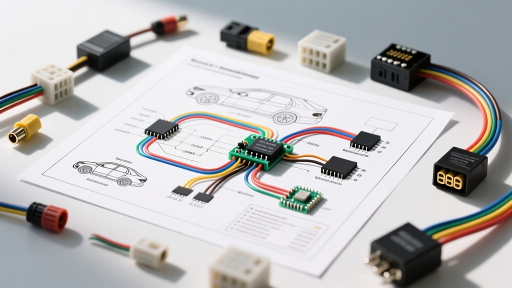
The Role of the Bypass Immobilizer Wiring Diagram PDF in Module Selection
When performing an engine swap, installing a remote start system, or replacing a damaged ECU, technicians and advanced DIYers inevitably search for a bypass immobilizer wiring diagram pdf to understand the factory security architecture. However, a schematic alone is only half the battle. The factory immobilizer—whether a low-frequency transponder ring or a high-speed CAN-bus encrypted network—requires a specific hardware solution to bypass or emulate the security handshake. Selecting the wrong bypass module can result in data bus collisions, parasitic battery drains, or a permanently bricked ECU.
As an automotive electrical specialist, I evaluate immobilizer bypass products not just by their marketing claims, but by how they integrate with the vehicle's native wiring. This guide compares the three primary immobilizer bypass technologies and details how to interpret your wiring diagram PDF to execute a flawless, OEM-grade installation.
Comparing Immobilizer Bypass Technologies
Before cutting into a single wire, you must match the bypass product to the vehicle's security generation. Below is a technical comparison of the three dominant immobilizer bypass modules available on the market.
| Bypass Technology | Best Application | Wiring Complexity | Diagram Focus Area |
|---|---|---|---|
| RF Transponder Cloner | Older vehicles (1995-2005) with glass/carbon chip keys (e.g., Ford PATS Gen 1/2, Toyota TVSS). | Low (2-4 wires) | Transceiver ring power, ground, and antenna coil routing. |
| Hardwire Relay Bypass | Universal applications where a spare key is sacrificed and wired into a relay harness. | High (Relay logic, 8+ wires) | Ignition switch cylinder pinouts, starter interrupt circuits. |
| CAN-Bus Digital Emulator | Modern vehicles (2006+) utilizing encrypted rolling codes via OBD2 or high-speed CAN networks. | Medium (Data lines only) | CAN-H/CAN-L routing, OBD2 port pinouts, termination resistors. |
If your bypass immobilizer wiring diagram pdf shows a simple 4-pin transceiver connector at the ignition cylinder, an RF Cloner or Hardwire Relay is your target product. If the diagram shows the immobilizer module communicating via twisted-pair data lines to the PCM, you must select a CAN-Bus Digital Emulator.
Decoding the Schematic: Wire Colors, AWG, and Pinouts
Factory service manuals and PDF schematics use standardized DIN/ISO symbols, but wire colors and gauges vary wildly between manufacturers. Understanding how to translate the PDF into physical wire prep is critical for signal integrity.
Ford PATS Transceiver Ring Integration (Hardwire/RF Cloner)
Let's examine the Ford Passive Anti-Theft System (PATS) Generation 2, commonly found in late-90s to early-2000s F-150s and Mustangs. When reviewing the PATS bypass immobilizer wiring diagram pdf, you will locate the transceiver ring connector at the base of the ignition lock cylinder. It is a 4-pin micro-timer connector.
- Pin 1 (Ground): Black/White wire. Requires a dedicated chassis ground, not a shared daisy-chain ground. Use 18 AWG.
- Pin 2 (TX - Transmit): Gray/Orange wire. Carries the 125 kHz excitation signal from the transceiver to the transponder. Use 22 AWG.
- Pin 3 (RX - Receive): White/Light Green wire. Returns the transponder's unique 64-bit ID code to the transceiver. Use 22 AWG.
- Pin 4 (Power): Red/Light Green wire. Switched 12V+ from the ignition run/start circuit. Use 18 AWG.
Expert Insight: When installing an RF cloner module, the TX and RX lines are highly susceptible to electromagnetic interference (EMI). Never route these 22 AWG data wires parallel to high-current 10 AWG ignition or starter cables. Maintain a minimum 4-inch separation to prevent signal degradation, which will result in a 'No Start' condition and a flashing theft indicator.
CAN-Bus Digital Emulator Integration
For modern vehicles, such as the 2015+ GM Global B architecture or VW MQB platforms, the immobilizer is deeply embedded in the CAN-bus network. Your bypass immobilizer wiring diagram pdf will direct you to the OBD2 diagnostic port or the PCM gateway.
According to SAE J2284 standards for High-Speed CAN, the data bus operates using a twisted pair:
- CAN-High (OBD2 Pin 6): Dominant state ~3.5V, Recessive state ~2.5V.
- CAN-Low (OBD2 Pin 14): Dominant state ~1.5V, Recessive state ~2.5V.
When tapping these lines for a digital bypass module, you must use 22 AWG or 24 AWG twisted-pair wire. The untwisted 'pigtail' length at your solder joint must not exceed 1.5 inches to prevent signal reflection and bus termination faults. Furthermore, the CAN network relies on a 120-ohm termination resistor at both ends of the bus. If your multimeter reads 120 ohms between Pin 6 and Pin 14, the network is intact. If it reads 60 ohms, the resistors are in parallel and functioning perfectly. A reading of infinite resistance indicates a broken CAN line.
Installation Standards and Failure Prevention
The most common cause of immobilizer bypass failure is not the module itself, but poor electrical workmanship. The Mobile Electronics Certified Professional (MECP) guidelines strictly dictate how security and data circuits should be terminated.
The Dangers of T-Taps and Scutch-Loks
Never use mechanical T-taps, scotch locks, or vampire clips on immobilizer data lines. These connectors rely on a small metal blade piercing the wire insulation, which inevitably severs strands of the 22 AWG copper. This increases resistance and creates a point of failure for high-frequency data signals. Furthermore, they allow moisture ingress, leading to copper oxidation (green crust) that alters the impedance of the CAN-bus.
Correct Method: Strip the wire, use a military-spec solder sleeve with an integrated heat-shrink seal, or perform a Western Union splice followed by rosin-core soldering and adhesive-lined heat shrink. This ensures a gas-tight connection that will survive the thermal expansion and contraction cycles of the engine bay.
Voltage Drop and the 'Sleep Mode' Parasitic Draw
Digital bypass modules must interface with the vehicle's ignition sense and accessory circuits to know when to wake up and inject the security token. If your wiring diagram PDF indicates an 'Ignition 1' sense wire, you must verify the circuit's behavior during the 'Crank' position. Many factory ignition switches drop accessory and secondary ignition circuits during cranking to preserve battery voltage for the starter motor.
If your bypass module loses its 12V reference during cranking, it will reboot, fail to send the immobilizer bypass token, and the ECU will kill the fuel injectors immediately after the engine fires. To solve this, use a 30A automotive relay to hold the 12V sense line active during the crank cycle, or ensure your bypass module features an internal 'crank-safe' capacitor buffer.
Troubleshooting the Bypass Integration
Even with the correct module and a flawless interpretation of the bypass immobilizer wiring diagram pdf, issues can arise. Use this diagnostic tree to isolate faults:
- Symptom: Engine cranks but immediately dies.
Cause: The immobilizer handshake failed. The ECU received an invalid or missing transponder ID.
Fix: Verify the CAN-bus termination resistance. Check for reversed CAN-H and CAN-L pins at the bypass module harness. On RF systems, ensure the cloner antenna is positioned within 1 inch of the factory transceiver ring. - Symptom: Engine does not crank; security light flashes rapidly.
Cause: The PCM has detected an open or short in the transceiver circuit.
Fix: Check the 18 AWG power and ground feeds to the transceiver. A blown 10A fuse in the cabin junction box (often labeled 'SEC' or 'PATS') will kill the entire system. - Symptom: Intermittent no-start when the engine is hot.
Cause: Thermal expansion is breaking a poor solder joint or causing a cheap relay to bind.
Fix: Inspect all ground points. Sand away paint and clear coat to bare metal, and apply dielectric grease to prevent galvanic corrosion.
Final Selection Advice
When sourcing your hardware, always prioritize modules that offer firmware updatability via USB or cloud connection. As manufacturers push OTA (Over-The-Air) security patches to modern ECUs, a static bypass module may become obsolete overnight. By combining a high-quality, updatable digital emulator with a meticulous reading of your vehicle's specific bypass immobilizer wiring diagram pdf, you ensure a reliable, secure, and professional-grade integration that respects the vehicle's native electrical architecture.
For further reading on factory security protocols, consult the Ford Motorcraft Service Information portal or your specific OEM's technical service bulletins regarding anti-theft system recalibrations.