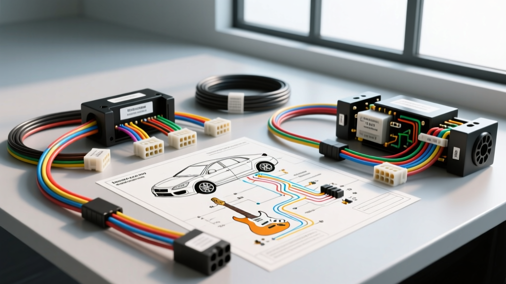
The Mobile Studio Dilemma: High-Z Meets High-EMI
Building a mobile recording studio inside a Sprinter van or integrating a custom electric guitar effects loop into a vehicle's 12V audio system presents a unique set of electrical challenges. When you pull up a standard wiring diagram guitar schematic—such as a classic passive harness utilizing 250kΩ audio taper potentiometers and 0.047μF tone capacitors—you are looking at a high-impedance (High-Z), unbalanced circuit. In a controlled indoor environment, this setup operates flawlessly. However, the automotive electrical environment is incredibly hostile to microvolt and millivolt audio signals.
A vehicle's 12V DC system is plagued by Electromagnetic Interference (EMI), Radio Frequency Interference (RFI), and severe voltage fluctuations. The alternator's 3-phase rectifier generates AC ripple, ignition coils emit high-frequency RF spikes, and PWM (Pulse Width Modulation) fuel pumps introduce low-frequency noise. If you connect a passive guitar directly to a vehicle's auxiliary input or an unbuffered Digital Signal Processor (DSP) without proper impedance matching and shielding, the result is catastrophic alternator whine and signal degradation. This guide provides a step-by-step troubleshooting flow to diagnose and resolve these issues, ensuring pristine audio quality for mobile musicians.
Step-by-Step Troubleshooting Flow: Eliminating Alternator Whine
Step 1: Verify the 12V Ground Star Topology
Alternator whine that changes pitch with engine RPM is almost exclusively a ground loop issue. In a mobile studio build, the guitar amplifier, DSP, and vehicle head unit must share a single, unified ground point to prevent differential voltage potentials. If the DSP is grounded to a seatbelt bolt (typically 10 AWG or 12 AWG factory wire) and the amp is grounded to the chassis near the wheel well, a ground loop is formed through the vehicle's sheet metal.
- Action: Establish a "Star Ground" topology. Run dedicated 8 AWG OFC (Oxygen-Free Copper) ground wires from the DSP, the active DI (Direct Injection) box, and the power amplifier to a single, massive grounding distribution block.
- Preparation: Sand away all factory e-coat paint and rust down to bare, shiny steel. Use a stainless steel terminal and a torque wrench to secure the ring terminal (typically M8 or M10 bolt, torqued to 15-20 ft-lbs depending on the chassis thickness).
- Verification: With the engine running and accessories (A/C, headlights) on, measure the DC voltage drop between the DSP chassis and the battery negative terminal. It must read less than 0.05V (50mV). If it reads higher, clean the ground or increase the wire gauge.
Step 2: Measure AC Ripple on the 12V Rail
If the ground topology is verified but a high-pitched whine persists, the issue may be failing alternator diodes or excessive AC ripple on the 12V DC supply feeding your active guitar preamps or DSP. A healthy automotive charging system should produce less than 50mV of AC ripple. Failing diodes can push this over 200mV, which easily bleeds into high-gain guitar circuits. An alternator spinning at 2,000 RPM (33.3 Hz) with 6 diodes produces a ripple frequency of roughly 200 Hz. This falls squarely in the lower-midrange of a guitar's frequency response, making it highly audible and destructive to the mix.
- Set a digital oscilloscope or a high-quality multimeter to AC Voltage mode.
- Probe the main 12V power distribution block feeding your audio equipment and the star ground point.
- Rev the engine to 2,500 RPM. Observe the waveform. A healthy alternator shows a relatively flat line with minor fuzz. A failing rectifier shows massive, rhythmic spikes corresponding to the 6-pulse rectification frequency.
- Fix: If ripple exceeds 50mV, install a 12V inline power filter (LC circuit choke and large electrolytic capacitors, typically 22,000μF) rated for the amperage of your audio draw, or replace the vehicle's alternator rectifier bridge.
Step 3: Implement Impedance Matching and Signal Isolation
A standard wiring diagram guitar setup outputs an unbalanced, high-impedance signal (often between 10kΩ and 100kΩ depending on the pickups and pot settings). Feeding this directly into a standard automotive DSP RCA input (which expects a low-impedance source of 100Ω to 600Ω) will result in severe high-frequency roll-off (the "tone suck" effect) and act as an antenna for ignition EMI.
- Buffer the Signal: Install an active, high-headroom DI box or a dedicated High-Z to Low-Z impedance matching buffer near the guitar's input jack. This converts the signal to a low-impedance, balanced output.
- Shielding Protocol: Never use standard unshielded 22 AWG guitar wire for runs longer than 12 inches inside a vehicle. Use double-shielded coaxial cable (braid plus foil) for all signal runs. The braided shield handles low-frequency EMI (alternator), while the foil shield handles high-frequency RFI (ignition coils and spark plug wires).
- Drain Wire Termination: Connect the shield's drain wire to the chassis ground at the DSP end only (Pin 3 on a balanced XLR/TRS connector) to prevent the shield itself from becoming a ground loop antenna.
Technical Reference: Custom DSP Integration Harness
When wiring an active guitar buffer into a high-end automotive DSP (such as a Helix PRO or JL Audio TwK), precise pinout and wire gauge selection is critical to maintain signal integrity. Below is the specification chart for a custom balanced input harness.
| Pin / Function | Wire Color (Custom Loom) | AWG Size | Signal Type | Termination Notes |
|---|---|---|---|---|
| Pin 1: Signal + (Hot) | White w/ Blue Stripe | 22 AWG Stranded | Balanced Audio (+) | Soldered to Neutrik XLR, heat-shrink sealed |
| Pin 2: Signal - (Cold) | Black w/ Blue Stripe | 22 AWG Stranded | Balanced Audio (-) | Twisted pair with Signal + to reject common-mode EMI |
| Pin 3: Shield / Drain | Bare Copper Braid | 20 AWG Drain | EMI Shield Ground | Connected to DSP chassis ground at input jack ONLY |
| Pin 4: 12V Remote Turn-On | Blue (Standard Auto) | 18 AWG OFC | +12V DC Trigger | Fused at 2A, sourced from DSP accessory output |
Common Failure Modes in Mobile Guitar Rigs
Potentiometer Scratch and DC Offset
Automotive environments experience massive temperature swings (-20°F to 140°F+ inside a parked vehicle). Standard carbon-track guitar potentiometers (250kΩ/500kΩ) are not sealed against humidity or extreme thermal cycling. Moisture intrusion leads to oxidation, causing severe "scratchiness" when adjusting volume or tone. Furthermore, if a DSP or active buffer has a failing DC blocking capacitor, it can leak DC voltage back into the passive guitar harness, magnetizing the pickups and ruining the tone. Always use sealed, conductive plastic or cermet potentiometers for permanently mounted vehicle audio controls.
Capacitor Microphonics and Dielectric Breakdown
Standard ceramic disc capacitors (often used in traditional tone circuits) can become microphonic under heavy bass vibrations from the vehicle's subwoofer system, acting as unintended contact microphones. This piezoelectric effect injects low-frequency rumble directly into the guitar signal chain. Upgrade to polypropylene film or metallized polyester film capacitors (like Orange Drop or Mallory 150 series) which are mechanically stable and immune to vibration-induced noise.
Vibration-Induced Solder Joint Fatigue
Standard 60/40 rosin-core solder used in indoor guitar wiring is brittle and prone to micro-fractures under the constant 20Hz-50Hz vibration of a vehicle chassis. For automotive audio integration, all solder joints must be wrapped in adhesive-lined dual-wall heat shrink tubing. In high-stress areas (like door jambs or hinge passes), use flexible silicone-jacketed wire rather than standard PVC push-back wire to prevent copper fatigue and strand breakage.
Authoritative References & Standards
- SAE International J1113: Electromagnetic Compatibility Measurement Procedures and Limits for Components. Essential for understanding EMI/RFI shielding requirements in 12V vehicular environments.
- Mobile Electronics Certified Associate (MECA): Industry standards for automotive audio grounding, star-topology implementation, and alternator noise diagnostics.
- Consumer Technology Association (CTA-2015): Standards for mobile electronics power wire gauge, current capacity, and color-coding in 12V DC automotive applications.