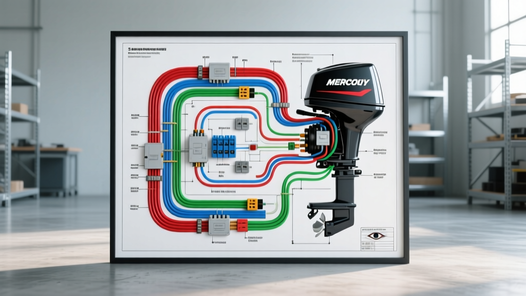
Mastering the 2 Stroke Mercury Outboard Wiring Diagram Schematic
Diagnosing electrical faults on a carbureted or early EFI 2-stroke Mercury outboard requires more than a basic digital multimeter (DMM). Unlike standard 12V DC automotive circuits, Mercury's Capacitor Discharge Ignition (CDI) systems rely on high-voltage, high-frequency AC pulses generated by the stator and shaped by the trigger. To effectively trace faults, you must interpret a 2 stroke Mercury outboard wiring diagram schematic through a systematic troubleshooting flow. This guide provides a step-by-step diagnostic decision tree, focusing on the ignition switch, stator, trigger, switchbox (CDI), and ignition coils.
Required Diagnostic Tools
Before probing any wires, ensure you have the correct equipment. Standard DMMs average out AC voltage pulses, leading to false low readings on CDI systems.
- DVA (Direct Voltage Adapter): Essential for reading peak AC voltage from the stator and trigger. A standard DMM will show 40V where a DVA correctly shows 150V+.
- Piercing Probes: To test wires without stripping back the marine-grade insulation (typically 14 AWG to 16 AWG for ignition circuits).
- Ohmmeter/Continuity Tester: For checking the Black/Yellow kill circuit and ground paths.
- Timing Light: To verify spark output under cranking and running RPM conditions.
Core Wire Color Codes & Schematic Reference
The following table outlines the standard OEM wire color codes found in most Mercury V6 2-stroke outboard wiring schematics (90HP to 200HP). Always cross-reference with your specific service manual, as harness revisions occur.
| Component | Wire Color | Function | AWG / Spec |
|---|---|---|---|
| Ignition Switch | Red | Battery Positive (B+) Input | 10 AWG |
| Ignition Switch | Purple | Ignition On / Choke Output | 14 AWG |
| Kill Circuit | Black w/ Yellow Stripe | Capacitor Discharge Ground (Kill) | 14 AWG |
| Stator (High) | Red | High-Speed Stator Output to Switchbox | 16 AWG |
| Stator (Low) | Red w/ White Stripe | Low-Speed Stator Output to Switchbox | 16 AWG |
| Trigger | White, Violet, Brown | Timing Pulses (Cylinders 1, 3, 5) | 16 AWG |
| Stator to Rectifier | Yellow | AC Charging Output to Regulator | 12 AWG |
Step-by-Step Troubleshooting Flow
Follow this sequential decision tree when encountering a no-spark or intermittent spark condition. Never skip the kill circuit verification, as it accounts for over 60% of all marine no-start complaints.
Step 1: Verify the Kill Circuit (Black/Yellow)
Symptom: No spark on any cylinder.
Action: The Black/Yellow wire grounds the CDI capacitor to stop the engine. If this wire is shorted to ground anywhere in the harness, the engine will not spark.
- Disconnect the main harness plug (typically a 14-pin rectangular AMSEA or Mercury proprietary connector) from the engine.
- Check for spark with the harness disconnected. If spark returns, the fault is in the key switch, wiring harness, or emergency lanyard switch.
- If no spark persists, disconnect the Black/Yellow wire directly at the switchbox (CDI) terminal.
- Test again. If spark returns, the switchbox harness is shorted. If still no spark, proceed to Step 2.
Step 2: Stator Output Testing
Symptom: No spark, or spark drops out above 2500 RPM.
Action: Connect your DVA adapter to the multimeter. Set the meter to DC Volts (the DVA converts peak AC to readable DC).
- Low-Speed Stator (Red/White to Blue): Crank the engine. You should read a minimum of 150V DVA. If below 150V, the stator is failing or the air gap is incorrect (spec: 0.060 inches).
- High-Speed Stator (Red to Blue): Crank or run the engine. You should read 150V to 400V DVA. A reading below 150V indicates a shorted stator winding or a failed switchbox diode.
Step 3: Trigger Signal Verification
Symptom: Spark on some cylinders, but not others.
Action: The trigger generates the timing signal. Connect the DVA between the trigger wire (e.g., White) and the trigger ground (White/Black).
- Crank the engine. A healthy trigger produces 1.5V to 4.0V DVA.
- If the voltage is erratic or below 1.0V DVA, inspect the trigger vane ring for debris or replace the trigger assembly.
- Diagnostic Rule: If the stator reads correctly, but one specific cylinder lacks spark and its trigger wire reads 0V DVA, the trigger is at fault. If the trigger reads >1.5V DVA but the cylinder lacks spark, the switchbox or ignition coil is defective.
Step 4: Switchbox to Ignition Coil Routing
Symptom: Weak spark or backfiring.
Action: Inspect the primary ignition wires routing from the switchbox to the coils. Mercury uses specific color-coded primary wires for each cylinder (e.g., Cyl 1: Brown, Cyl 2: Brown/White). Ensure the 1/4-inch female spade connectors are tight and free of marine corrosion. Use a dielectric grease (like Mercury Perfect Seal) on all connections to prevent saltwater ingress.
Charging Circuit & Regulator/Rectifier Diagnostics
A complete 2 stroke Mercury outboard wiring diagram schematic also encompasses the charging system. The stator generates AC voltage via the Yellow wires, which is routed to the regulator/rectifier. This component converts AC to DC to charge the boat's battery and power accessories.
Testing the Yellow Stator Leads
- Resistance Check: With the engine off and the rectifier disconnected, measure the resistance between the two Yellow stator wires. The specification is typically 0.1 to 0.5 ohms. An open reading (OL) indicates a broken stator winding.
- Ground Check: Measure resistance from either Yellow wire to the engine block (ground). It must read infinite (OL). Any continuity to ground means the stator is shorted internally and must be replaced.
- AC Voltage Output: Set your DMM to AC Volts. With the engine running at 2000 RPM, the Yellow wires should output between 14V and 18V AC per phase. If one phase is significantly lower, the stator is failing.
Crucial Warning: Never disconnect the battery while the outboard is running. Doing so will cause a massive voltage spike from the stator, instantly destroying the regulator/rectifier and potentially frying the CDI switchbox and ignition coils.
Common Failure Modes & Connector Pinouts
When utilizing a 2 stroke Mercury outboard wiring diagram schematic, pay close attention to the main engine-to-boat harness connector. The 12-pin and 14-pin AMSEA/Mercury standard connectors are notorious for pin spread and corrosion.
- Pin A (Red): 12V B+ from battery. Voltage drop here causes weak CDI charging.
- Pin C (Purple): Ignition voltage. Must remain above 10.5V during cranking.
- Pin D (Black/Yellow): Kill circuit. Must show infinite resistance to ground when the key is in the 'Run' position.
- Rectifier Failures: The Yellow stator wires route to the rectifier/regulator. If a diode inside the rectifier shorts, it can feed AC voltage back into the CDI switchbox, destroying the internal capacitors. Always test the rectifier if you experience repeated switchbox failures.
Authoritative References & Standards
For comprehensive torque specifications, exact resistance values, and model-year-specific schematics, consult the following resources:
- CDI Electronics Mercury Troubleshooting Guide - The industry standard for DVA testing parameters and switchbox diagnostics.
- MarineEngine.com OEM Parts & Schematics - Excellent resource for identifying exact harness part numbers and connector pinouts.
- SAE J1128 Standard - Reference for low-tension primary cable specifications used in marine and automotive ignition harnesses.
Disclaimer: Always disconnect the negative battery terminal before performing continuity tests or replacing electrical components. Working on marine ignition systems involves high-voltage shocks; use insulated tools and wear appropriate PPE.