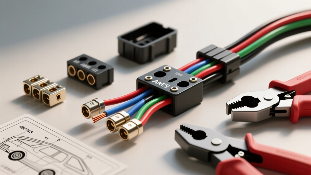
Decoding the 7-Pin Trailer Wiring Diagram: What You Actually Need
Reading a standard Curt Manufacturing wiring guide or consulting a factory trailer wiring diagram is only the first step in building a reliable tow harness. The true differentiator between a harness that fails in the first rainstorm and one that lasts a decade lies in your tooling and material selection. When upgrading from a basic 4-pin flat to a heavy-duty 7-way RV blade connector, the electrical demands increase exponentially. You are no longer just powering low-draw LED marker lights; you are managing high-amperage electric brake magnets and 12-volt auxiliary charging circuits. This cost and tool analysis breaks down exactly what you need to execute a professional-grade 7-pin harness build, avoiding the hidden expenses and cheap material traps that plague DIY towers.
The Professional Tool Arsenal
Standard household wire strippers and vinyl electrical tape have no place in a trailer harness. The environment underneath a tow vehicle is subjected to extreme thermal cycling, road salt, and high-pressure water intrusion. To ensure gas-tight connections that resist galvanic corrosion, you must invest in specific automotive electrical tooling.
1. Ratcheting Wire Crimpers (10-22 AWG)
A ratcheting crimper, such as the IWISS T10 or Knoweasy equivalent, is non-negotiable. Unlike standard plier-style crimpers, a ratcheting tool applies a precise, uniform crushing force to the terminal barrel, ensuring a gas-tight seal that prevents oxygen and moisture from reaching the copper strands. Budget approximately $35 to $50 for a quality ratcheting set with interchangeable dies for insulated and non-insulated terminals.
2. Dual-Wall Adhesive Heat Shrink & Heat Gun
Never use standard PVC electrical tape on trailer wiring; capillary action will wick moisture under the tape, resulting in the infamous 'green crust' corrosion. You must use dual-wall, adhesive-lined polyolefin heat shrink (3M or equivalent). When heated, the inner meltable adhesive wall flows into the wire strands, creating a waterproof environmental seal. A basic dual-temperature heat gun ($25-$40) is required to shrink these tubes evenly without scorching the insulation.
3. Digital Multimeter (Auto-Ranging)
Troubleshooting a trailer wiring diagram requires verifying voltage drop and continuity. An auto-ranging digital multimeter (DMM) like the Fluke 115 or a more budget-friendly Innova 3320 ($20-$30) allows you to test for parasitic draws and verify that your ground circuits are handling the return load without bottlenecking.
Material Cost Breakdown: Wire, Connectors, and Loom
Building a custom 25-foot 7-way harness requires specific American Wire Gauge (AWG) sizing to prevent voltage drop. Below is a realistic cost matrix for high-quality, SAE J583-compliant automotive primary wire and hardware.
| Component | Specification / Size | Est. Cost | Application Purpose |
|---|---|---|---|
| Primary Automotive Wire | 10 AWG (Blue & Black) | $18.00 / 25ft | Electric brakes & 12V Aux power |
| Primary Automotive Wire | 12 AWG (White) | $14.00 / 25ft | Main chassis ground return |
| Primary Automotive Wire | 14 AWG (Red, Brown, Green, Yellow) | $22.00 / 100ft total | Lighting circuits (Turn, Tail, Reverse) |
| 7-Way RV Blade Plug | Heavy-Duty Metal Housing | $24.00 | Trailer-side termination point |
| Adhesive Heat Shrink Kit | Assorted 3:1 Shrink Ratio | $16.00 | Waterproofing all crimped splices |
| Split Loom Tubing | 1/2 inch & 3/8 inch corrugated | $12.00 | Physical abrasion protection |
| Dielectric Grease | Permatex or Noalox (2oz tube) | $8.00 | Preventing pin oxidation at the plug |
| Total Estimated Material Cost | $114.00 - $135.00 | ||
SAE J286 7-Way RV Pinout & AWG Requirements
According to the SAE J286 Standard for 7-way connectors, specific pin assignments and color codes dictate the harness layout. Misrouting these wires or undersizing the gauge will lead to catastrophic failure modes, particularly with electric brake systems.
- Pin 1 (White) - Ground: 12 AWG minimum. This carries the return current for the entire lighting system. If undersized, voltage will backfeed through other circuits, causing 'ghost lighting' (e.g., brake lights illuminating when turning).
- Pin 2 (Blue) - Electric Brakes: 10 AWG strictly required. Electric brake magnets draw up to 12-15 amps per axle. Using 14 AWG wire over a 25-foot run introduces severe voltage drop, reducing the magnetic clamping force and resulting in dangerously weak braking performance.
- Pin 3 (Green) - Tail/Running Lights: 14 AWG. Standard low-draw circuit for clearance and marker LEDs.
- Pin 4 (Black) - 12V Battery Charge/Aux: 10 AWG. Used to maintain the trailer's breakaway battery or power interior 12V accessories.
- Pin 5 (Red) - Left Turn/Stop: 14 AWG.
- Pin 6 (Brown) - Right Turn/Stop: 14 AWG.
- Pin 7 (Yellow) - Reverse Lights/Aux: 14 AWG. Often used to trigger a reverse lockout solenoid on surge brake couplers.
Hidden Costs: Protecting the Tow Vehicle BCM
Many DIYers consult an etrailer wiring FAQ and assume they can simply tap the tow vehicle's 12-volt accessory wire directly into the Black (Pin 4) circuit. This is a critical error that can destroy modern Body Control Modules (BCMs). The hidden cost here is a heavy-duty relay kit and a 30-amp auto-reset circuit breaker ($25-$35). You must wire the Black 12V aux circuit through an auto-reset breaker mounted within 18 inches of the tow vehicle's battery positive terminal. If a trailer wire shorts against the steel frame, the breaker trips instantly, preventing a harness fire and saving your vehicle's $1,500 BCM from frying.
Real-World Failure Modes That Inflate Your Budget
Cutting corners on your trailer wiring diagram implementation leads to expensive diagnostic headaches down the road. Here are the most common budget-inflating failure modes:
The 'Chassis Ground' Fallacy
Many cheap, pre-fabricated harnesses rely on grounding the white wire to the trailer's steel frame via a single sheet metal screw. This fails rapidly due to rust and paint insulation. The correct, albeit slightly more expensive, method is to run the 12 AWG white ground wire all the way back to the trailer's breakaway switch and battery negative terminal, creating a dedicated, isolated ground loop that bypasses rusty frame hinges and pivot points.
Brake Magnet Voltage Starvation
If you use standard 14 AWG wire for the blue electric brake circuit, the resistance of the copper over a 30-foot round-trip will drop the voltage reaching the brake magnets from 12V down to roughly 9.5V under load. This starves the electromagnets, causing them to drag and overheat rather than clamp firmly. Spending the extra $8 on a 25-foot spool of 10 AWG blue wire prevents the premature $150 replacement of burnt-out brake backing plates.
Terminal Pull-Out and Vibration Fatigue
Using non-ratcheting crimpers or folding the wire over the terminal tab and soldering it creates brittle joints. The constant high-frequency vibration of a towed trailer will snap soldered joints within a few hundred miles. Ratcheting crimpers cold-weld the copper to the brass terminal, ensuring the physical connection survives the harsh dynamic loads of highway towing.