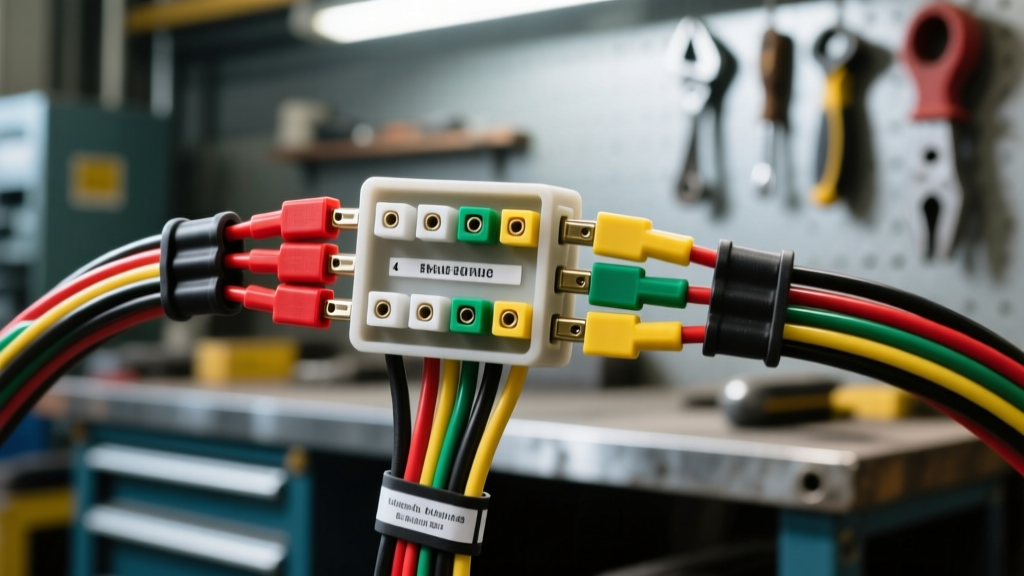
Understanding the Harbor Freight 4-Pin Flat Harness
When sourcing a reliable harbor freight trailer wiring diagram, most DIYers are working with the retailer's ubiquitous 4-way flat connector kits (such as part numbers 60355, 62757, or their wireless LED equivalents). These kits are popular for their affordability and plug-and-play promise for basic utility trailers, boat trailers, and small campers. However, the included instruction sheets often lack the technical depth required for a lasting, weather-resistant installation. Standard SAE J560 guidelines dictate specific pinouts and wire gauges, but budget kits frequently take liberties with wire composition that can lead to premature failure if not handled correctly.
Standard 4-Way Flat Pinout Reference
Before cutting or splicing any wires, verify the pinout on both the tow vehicle and the trailer side. The Harbor Freight 4-pin flat connector follows the standard North American color code:
| Pin Position | Wire Color | Function | Typical AWG (HF Kits) |
|---|---|---|---|
| 1 (Ground) | White | Chassis Ground Return | 16 AWG |
| 2 (Tail) | Brown | Tail / Running / License Plate Lights | 18 AWG |
| 3 (Left) | Yellow | Left Turn Signal & Stop Lamp | 18 AWG |
| 4 (Right) | Green | Right Turn Signal & Stop Lamp | 18 AWG |
The CCA Wire Challenge: What the Manual Doesn't Tell You
The most critical piece of information missing from the standard Harbor Freight trailer wiring diagram documentation is the metallurgy of the wire itself. To keep costs low, the 18 AWG wires in these kits are typically Copper-Clad Aluminum (CCA) rather than pure stranded copper. CCA wire has higher electrical resistance and is significantly more brittle. Furthermore, when CCA wire is spliced directly to the pure copper wiring of your vehicle's OEM harness using standard butt connectors, it creates a galvanic corrosion cell. Moisture ingress will cause the aluminum core to oxidize rapidly, leading to high-resistance joints, voltage drops, and dim trailer lights.
Expert Fix: Never use standard vinyl crimp connectors on CCA wire. You must use adhesive-lined marine-grade heat shrink terminals and apply a generous amount of dielectric grease to the splice point. For the most reliable connection, solder the CCA wire to a pure copper pigtail using rosin-core solder before sealing it, ensuring the solder wicks into the aluminum strands to prevent internal oxidation.
Step-by-Step Installation & Routing Guide
- Locate the OEM Tow Package Plug: Many modern trucks and SUVs have a blunt-cut 4-pin or 7-pin pigtail tucked behind the rear bumper or near the spare tire. If your vehicle lacks this, use a T-connector harness that plugs inline with the factory tail light assemblies to avoid cutting OEM wires.
- Prepare the CCA Wires: Use thermal wire strippers rather than blade-style strippers. Blade strippers tend to nick the brittle aluminum core of the HF harness, creating a weak point that will snap under road vibration.
- Splice and Seal: Connect Brown to Brown, Yellow to Yellow, and Green to Green. Use 18-16 AWG adhesive-lined heat shrink butt connectors. Apply heat evenly until the adhesive oozes from the ends, creating a watertight seal.
- Secure the Routing: Route the harness away from exhaust components (maintain at least a 12-inch clearance from hot pipes). Secure the wire loom to the chassis using UV-resistant zip-ties every 12 to 18 inches. Leave a slight service loop near the connector to prevent tension on the splice joints when turning.
- Establish the Ground (The Most Critical Step): Do not simply wrap the white wire around a rusty bolt. Find a clean, unpainted spot on the vehicle's frame rail. Sand it down to bare, shiny metal. Attach a 16 AWG copper ring terminal to the HF white wire, secure it with a stainless steel bolt, a star washer (to bite into the metal), and a nylon lock nut. Coat the terminal in dielectric grease after tightening to 15 ft-lbs.
Upgrading to a 7-Way RV Blade
If you are towing a camper with electric brakes, the 4-pin flat harness will not suffice. You will need to integrate a brake controller. According to etrailer's comprehensive wiring database, you can use a 4-to-7-way adapter, but for heavy-duty use, hardwiring a 7-way junction box is superior. You will retain the standard 4 colors for lighting, but must add:
- Blue Wire (12 AWG): Output to trailer electric brakes from the brake controller.
- Black Wire (10 AWG): 12V auxiliary power for charging trailer breakaway batteries or interior lights.
- Purple Wire (14 AWG): Reverse lights or reverse lockout for surge brake couplers.
When upgrading, bypass the thin 18 AWG wires from the Harbor Freight kit entirely for the power circuits, running dedicated 10 and 12 AWG pure copper wire directly to the vehicle's battery and brake controller via inline circuit breakers.
Troubleshooting Decision Matrix
Even with a perfect diagram interpretation, electrical gremlins occur. Use this diagnostic matrix to isolate faults in your HF harness installation:
| Symptom | Probable Cause | Diagnostic Test & Fix |
|---|---|---|
| All trailer lights are extremely dim or flicker when headlights turn on. | High-resistance ground connection or CCA galvanic corrosion on the white wire. | Test voltage drop between trailer chassis and vehicle battery negative. If >0.2V, sand ground point and upgrade white wire to 14 AWG pure copper. |
| Right turn signal blinks rapidly (hyperflash) on the tow vehicle dashboard. | Short circuit in the green wire, or LED trailer lights lacking proper resistors. | Disconnect trailer and test harness with a multimeter for continuity to ground. If LED, install a 50W 6-ohm load resistor on the green wire. |
| Running lights (brown wire) blow the vehicle's OEM fuse immediately. | Brown wire insulation chafed against the trailer tongue or hitch, causing a dead short. | Inspect the entire length of the brown wire, especially near the pivot point of the coupler. Wrap in split-loom tubing and apply chafe guards. |
| Turn signals work, but pressing the brake pedal turns off the turn signals on the trailer. | Feedback loop caused by a bad ground at the trailer light housing, forcing current to backfeed through the filament. | Clean the ground screw inside the trailer light housing. Ensure the metal light bucket is making solid contact with the trailer frame. |
Final Validation Testing
Do not rely on visual inspection alone. Once your harbor freight trailer wiring diagram installation is complete, use a digital multimeter to verify voltage at the trailer side of the plug. With the vehicle running and headlights on, the Brown pin should read between 13.2V and 14.1V. If it reads below 12V, you have excessive resistance in your splices or wire gauge. Furthermore, test the breakaway switch (if equipped) by pulling the pin and verifying that the trailer brakes lock up and the battery voltage holds steady under load. Proper execution of these steps ensures your budget-friendly harness performs like a premium OEM system, keeping you safe and DOT-compliant on the road.