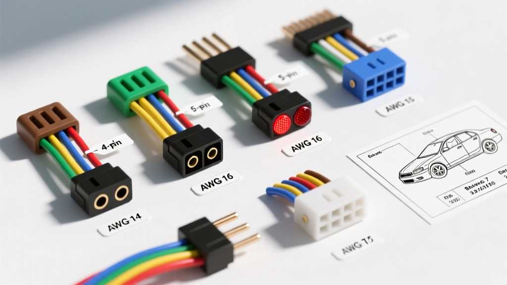
Introduction to RVIA and SAE Trailer Wiring Standards
When installing, repairing, or upgrading a trailer lighting and braking system, understanding the standard trailer wiring harness color code is critical for safety and compliance. In North America, the Recreation Vehicle Industry Association (RVIA) and the Society of Automotive Engineers (SAE) establish the baseline specifications for trailer connectors. Adhering to the RVIA ANSI Low Voltage Standard ensures that your tow vehicle and trailer communicate correctly, preventing short circuits, blown fuses, and catastrophic brake failures. This technical reference outlines the exact color codes, pin configurations, and American Wire Gauge (AWG) requirements for 4-pin, 5-pin, 6-pin, and 7-pin trailer connectors.
4-Pin Flat Connector: Standard Lighting
The 4-pin flat connector is the most common configuration for light-duty utility trailers, small boat trailers, and cargo carriers. It handles basic lighting functions but does not support electric brakes or 12-volt auxiliary power. A crucial technical detail for 4-pin harnesses is the ground wire. Because the ground wire carries the return current for all three lighting circuits simultaneously, it must be sized larger than the individual signal wires to prevent voltage drop and dimming.
| Pin Position | Wire Color | Function | Minimum AWG |
|---|---|---|---|
| Pin 1 (Ground) | White | Chassis Ground Return | 14 AWG (12 AWG preferred) |
| Pin 2 | Brown | Taillights, Running Lights, Markers | 16 AWG |
| Pin 3 | Yellow | Left Turn Signal & Stop Lamp | 16 AWG |
| Pin 4 | Green | Right Turn Signal & Stop Lamp | 16 AWG |
Expert Insight: Many modern 4-pin harnesses utilize a 'wishbone' design. In a wishbone harness, the brown running light wire splits into two separate wires (often brown with a yellow stripe and brown with a green stripe) near the connector. This allows you to run the running light circuit down both sides of the trailer independently, eliminating the need to splice a jumper wire across the rear bumper.
5-Pin Flat Connector: Surge Brake Lockout
The 5-pin flat connector builds upon the 4-pin standard by adding a fifth circuit, typically used for reverse lockout on hydraulic surge brakes. When the tow vehicle is placed in reverse, the 5th pin receives 12V power, which activates a solenoid on the trailer's surge brake coupler, preventing the brakes from engaging while backing up.
| Pin Position | Wire Color | Function | Minimum AWG |
|---|---|---|---|
| Pin 1 | White | Chassis Ground Return | 12 AWG |
| Pin 2 | Brown | Taillights & Running Lights | 16 AWG |
| Pin 3 | Yellow | Left Turn & Stop | 16 AWG |
| Pin 4 | Green | Right Turn & Stop | 16 AWG |
| Pin 5 | Blue | Reverse Lockout / Electric Brakes | 14 AWG |
While the blue wire is standard for electric brakes on larger connectors, on a 5-pin flat setup, it is almost exclusively wired to the vehicle's reverse light circuit to trigger the surge brake lockout solenoid.
6-Pin Round Connector: Heavy-Duty & Agricultural
The 6-pin round connector is frequently found on older heavy-duty equipment, agricultural trailers, and horse trailers. The pin layout can vary slightly between manufacturers, but the RVIA standard color code remains consistent. The larger round pins are designed to handle higher amperage and resist environmental corrosion better than flat blade connectors.
| Pin Clock Position | Wire Color | Function |
|---|---|---|
| Center | White | Ground |
| 2 o'clock | Brown | Taillights & Markers |
| 4 o'clock | Green | Right Turn & Stop |
| 6 o'clock | Red or Black | 12V Auxiliary Power |
| 8 o'clock | Yellow | Left Turn & Stop |
| 10 o'clock | Blue | Electric Brakes |
7-Pin RV Blade Connector: The Modern Standard
The 7-way RV blade connector is the undisputed standard for modern travel trailers, fifth wheels, and heavy car haulers. It supports all lighting circuits, 12-volt auxiliary power for charging the trailer battery, and a dedicated high-amperage circuit for electric trailer brakes. According to etrailer.com's comprehensive wiring guidelines, the physical layout of the 7-way connector follows a strict clock-face orientation to ensure cross-compatibility between different truck and trailer manufacturers.
| Pin Location | Wire Color | Function | Recommended AWG |
|---|---|---|---|
| Center Pin | White | Chassis Ground (Heavy Duty) | 10 AWG or 8 AWG |
| 1 o'clock | Black | 12V Battery Charge / Aux Power | 12 AWG (10 AWG for >25ft) |
| 3 o'clock | Yellow | Left Turn Signal & Stop Lamp | 14 AWG |
| 5 o'clock | Green | Right Turn Signal & Stop Lamp | 14 AWG |
| 7 o'clock | Brown | Taillights, Running Lights, Markers | 14 AWG |
| 9 o'clock | Blue | Electric Trailer Brakes | 12 AWG (10 AWG for >25ft) |
| 11 o'clock | Red or Purple | Reverse Lights / Auxiliary Aux | 14 AWG |
Technical Warning: The white ground wire on a 7-pin connector is the most critical wire in the entire harness. It must be bonded directly to the trailer's bare metal chassis using a ring terminal and a self-tapping screw or bolt. Relying solely on the hitch ball for grounding will result in severe voltage drop, causing the electric brakes to fail and LED lights to flicker or strobe.
Wire Gauge (AWG) and Voltage Drop Considerations
Using the correct trailer wiring harness color code is only half the battle; selecting the proper wire gauge is equally vital. Electric brake circuits utilize Pulse Width Modulation (PWM) from modern proportional brake controllers. This rapid pulsing generates heat. If the blue brake wire is undersized, the resistance will increase, causing a voltage drop at the brake magnets. This results in weak braking performance and overheated wires.
| Circuit Type | Standard AWG | Heavy-Duty / Long Run AWG | Max Amperage Load |
|---|---|---|---|
| Ground (White) | 10 AWG | 8 AWG | 30A - 40A |
| Electric Brakes (Blue) | 12 AWG | 10 AWG | 15A - 20A per axle |
| 12V Aux (Black) | 12 AWG | 10 AWG | 15A - 30A |
| Lighting (Brown/Yellow/Green) | 16 AWG | 14 AWG | 5A - 8A total |
Always use stranded, pure copper wire (GXL or SXL cross-linked polyethylene insulation) for trailer harnesses. Avoid Copper-Clad Aluminum (CCA) wire, which is brittle, prone to corrosion under vibration, and has a higher resistance that severely impacts brake controller performance. For more on material standards, refer to the SAE International Standards for automotive wire specifications (SAE J1128).
Troubleshooting Non-Standard and Faded Wiring
In the real world, custom-built trailers, imported equipment, or severely weathered harnesses may not follow the standard RVIA color codes. When you encounter a harness where the colors are faded, painted over, or entirely non-standard, you must map the pinout manually using a Digital Multimeter (DMM).
Step-by-Step Pinout Verification
- Identify the Ground: Set your DMM to the continuity (ohms) setting. Probe each pin on the trailer-side connector against a known bare-metal point on the trailer chassis. The pin that reads near 0.0 ohms is your ground (Standard: White).
- Test for 12V Aux and Brake Power: Set the DMM to DC Volts. With the tow vehicle running and the trailer connected, probe the remaining pins against the verified ground. The pin showing a constant 12.0V - 13.5V is your 12V Aux (Standard: Black). If you manually activate the brake controller override slider in the cab, the pin that spikes to 12V is your electric brake circuit (Standard: Blue).
- Map the Lighting: Turn on the tow vehicle's headlights. The pin that now shows 12V is the running light circuit (Standard: Brown). Finally, activate the left and right turn signals to map the remaining two pins (Standard: Yellow and Green).
Once mapped, label the wires immediately with heat-shrink tubing or wire markers, and consider replacing the entire harness with a compliant, color-coded molded plug to ensure long-term reliability and safety on the road.