The Fatal Flaw: NEC Residential Wire Gauge vs. SAE Automotive Standards
The fundamental misunderstanding arises from the difference between AC and DC power delivery, as well as the physical construction of the wire itself. A standard residential wire gauge chart (based on NEC Table 310.15(B)(16)) dictates that 10 AWG THHN wire can safely carry 40 amps in a 90°C environment. However, this assumes a 120V or 240V AC system. In a 12V DC automotive system, carrying the same wattage requires ten times the amperage. For example, a 1,200W inverter pulls roughly 10 amps on a 120V AC residential circuit (requiring 14 AWG or 12 AWG wire). That exact same 1,200W inverter, operating on a 12V DC vehicle chassis, will pull over 100 amps (accounting for inverter inefficiency). If a builder uses a residential wire gauge mindset and runs 6 AWG wire based on NEC AC charts, the 12V DC system will suffer severe voltage drop, triggering low-voltage shutdowns and generating massive heat. Furthermore, residential NM-B (Romex) or THHN wire is typically solid-core or low-strand count, designed to be pulled through stationary PVC conduit. Automotive environments demand high-strand-count, cross-linked polyethylene (XLPE) insulated wire like TXL or GPT, which must withstand continuous vibration, engine bay temperatures, and exposure to oil and road salts. The governing standard for automotive wire is SAE J1128, not the NEC.Complete Wiring Diagram Walkthrough: 12V Auxiliary Power Distribution
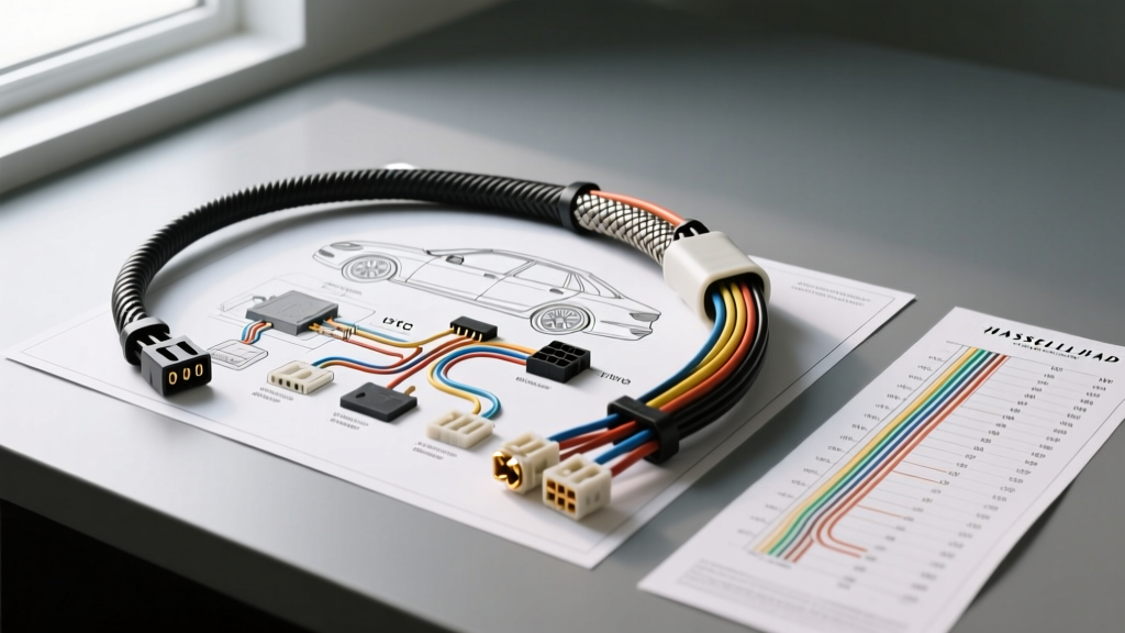
Let us walk through a standard dual-battery auxiliary wiring diagram, utilizing a Blue Sea Systems Automatic Charging Relay (ACR) and a 12-circuit auxiliary fuse block. We will analyze each segment to show where residential wire gauge logic fails and how proper automotive gauge selection is applied.Node 1: Alternator to Battery Isolator (High Current DC)
In our diagram, the alternator outputs up to 180 amps at 14.2V. The wire runs 12 feet from the alternator B+ terminal to the ACR isolator, and another 8 feet to the house battery bank. If you consult a residential wire gauge chart for 180 amps at 240V, you might select 2/0 AWG copper. However, in a 12V DC system, voltage drop is the primary limiting factor, not just thermal ampacity. A 3% voltage drop at 14.2V is only 0.42V. Using the standard voltage drop formula, a 20-foot round trip carrying 150 amps continuous requires 2/0 AWG SAE battery cable (SGX type) just to maintain a 2% drop. Crucially, the color coding here must follow SAE standards: Red for the B+ positive feed, and a heavy Black or chassis-ground strap for the return path. In residential wiring, Black is "hot" and White is "neutral." If an RV technician uses residential color codes (Black for +12V) and later hands the vehicle over to an automotive mechanic who assumes Black is Ground (SAE standard), the result will be a dead short the moment a multimeter probe or chassis contact is made.Node 2: Auxiliary Fuse Block to 12V Loads (Lighting and Fridge)
Moving down the diagram to the auxiliary fuse block, we are routing power to a 12V compressor fridge (drawing 6A continuous) and a bank of LED puck lights (drawing 2A). The wire run to the fridge is 15 feet one-way. A residential wire gauge chart would suggest 14 AWG is perfectly safe for a 15-amp circuit. But let us calculate the 12V DC voltage drop for 14 AWG over a 30-foot round trip at 6 amps. The resistance of 14 AWG copper is roughly 2.525 ohms per 1,000 feet. Voltage Drop = (2 x 15 ft x 6A x 2.525) / 1000 = 0.45V. A 0.45V drop on a 12V system is a 3.75% loss. Many modern 12V compressor fridges (like Dometic or ARB) have low-voltage protection that will shut the unit off if voltage at the terminal drops below 11.5V. Therefore, despite the "ampacity" being fine for thermal limits, the correct automotive wire gauge for this 15-foot run is 10 AWG TXL to keep the voltage drop under 2%. We terminate this 10 AWG TXL wire using a Delphi Metri-Pack 280 series connector, crimping the stranded wire with a proper ratcheting crimper to ensure gas-tight connections.12V DC Voltage Drop & Ampacity Comparison Chart
The table below illustrates the stark contrast between NEC residential ampacity limits and practical SAE automotive 12V DC limits for a standard 10-foot one-way (20-foot round trip) wire run, targeting a strict 3% maximum voltage drop (0.36V at 12V).| AWG Size | NEC Residential Ampacity (THHN 90°C) | SAE Automotive Ampacity (TXL 125°C) | Max 12V DC Current (10ft run, 3% Drop) | Typical Automotive Application |
|---|---|---|---|---|
| 16 AWG | Not Rated (NEC Min 14 AWG) | 10 Amps | 1.5 Amps | LED Lighting, ECU Sensor Signals |
| 14 AWG | 15 Amps | 15 Amps | 2.5 Amps | Interior Accent Lights, Horn Relay Trigger |
| 12 AWG | 20 Amps | 25 Amps | 4.0 Amps | 12V Accessory Sockets, Low-Draw Fuel Pumps |
| 10 AWG | 30 Amps | 40 Amps | 6.5 Amps | 12V Compressor Fridges, Amplifier Power |
| 8 AWG | 40 Amps | 55 Amps | 10.0 Amps | Winch Controls, Solar Charge Controllers |
| 4 AWG | 85 Amps | 100 Amps | 25.0 Amps | Inverter Feeds, Battery Bank Paralleling |
Note: The "Max 12V DC Current" column is the true limiting factor for automotive wire gauge selection. As shown, 10 AWG wire can thermally handle 40A, but will suffer unacceptable voltage drop if you push more than 6.5A over a 10-foot distance in a 12V system.
Real-World Failure Modes: Using Residential Wire in Vehicles
When builders ignore automotive specifications and utilize residential wire gauge logic and materials (like solid-core Romex or THHN) in vehicle builds, specific failure modes inevitably emerge on the trail or highway.- Vibration Fatigue and Conductor Snapping: Residential solid-core wire work-hardens and snaps under the constant high-frequency vibration of a diesel or gasoline engine chassis. Automotive GPT and TXL wire feature upwards of 100+ fine copper strands (e.g., 10 AWG TXL has 105 strands) designed to flex continuously without breaking.
- Insulation Degradation: THHN (Thermoplastic High Heat-resistant Nylon) insulation becomes brittle when exposed to automotive fluids like oil, transmission fluid, and brake cleaner. SAE J1128 rated wires utilize XLPE (Cross-linked Polyethylene) which is highly resistant to chemicals, abrasion, and under-hood temperatures exceeding 125°C.
- Crimp Terminal Failure: Automotive connectors, such as Weather-Pack and Metri-Pack terminals, utilize specific crimp tabs designed to bite into and deform around stranded copper. If you attempt to crimp a solid residential wire into a standard automotive blade terminal, the terminal will not grip properly. The wire will pull out under mild tension, or worse, arc internally, melting the connector housing.
- The "Black Wire" Short Circuit: As mentioned, NEC residential wiring uses Black for the hot (positive) wire. SAE automotive standards use Black for the ground (negative) return. Mixing these paradigms in a single vehicle diagram guarantees that a future technician will cause a dead short when troubleshooting with a test light or multimeter.