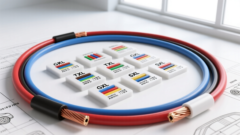
The Critical Role of Car Wire Gauge in Automotive Systems
Selecting the correct car wire gauge is the fundamental difference between a reliable, high-performance automotive electrical system and a melted harness that leaves you stranded. Unlike residential wiring, automotive electrical systems operate in harsh environments characterized by extreme temperature fluctuations, constant vibration, and exposure to corrosive fluids. The American Wire Gauge (AWG) system dictates the physical diameter of the copper conductor, which directly correlates to its electrical resistance and current-carrying capacity (ampacity). However, in automotive applications, the copper gauge is only half the equation; the insulation jacket material is equally critical. This comprehensive product comparison and selection guide will break down the exact specifications, insulation types, and application-specific requirements for choosing the optimal car wire gauge for your vehicle.
AWG vs. Metric: Decoding Automotive Wire Sizing
While the North American aftermarket heavily relies on the AWG system, modern OEM manufacturing (especially European and Asian platforms) often utilizes metric cross-sectional area measurements (mm²). Understanding the crossover is vital when repairing modern harnesses or integrating OEM pigtails into aftermarket setups. For example, a standard 18 AWG wire equates to approximately 0.82 mm², which OEMs often round to 0.75 mm² or 0.80 mm² specifications. When splicing metric OEM wire to AWG aftermarket wire, always match the cross-sectional area as closely as possible to prevent localized resistance hotspots.
Insulation Jacket Comparison: GXL vs. TXL vs. SXL vs. PVC
The most common mistake made by amateur builders is using standard PVC-insulated wire (like THHN or primary wire) in an engine bay. Standard PVC melts at around 105°C (221°F), a temperature easily exceeded near exhaust manifolds or turbochargers. Automotive-spec wire utilizes Cross-Linked Polyethylene (XLPE), which offers superior thermal and abrasion resistance. According to the SAE International J1128 Standard, automotive wire is classified into three primary XLPE categories:
| Wire Type | Insulation Material | Wall Thickness | Max Temp Rating | Best Application |
|---|---|---|---|---|
| GXL | XLPE (Thin Wall) | 0.58 mm (18 AWG) | 125°C (257°F) | General engine bay, ECU harnesses, tight looms |
| TXL | XLPE (Extra Thin) | 0.41 mm (18 AWG) | 125°C (257°F) | Modern OEM harnesses, high-density connector cavities |
| SXL | XLPE (Standard Wall) | 0.79 mm (18 AWG) | 125°C (257°F) | Motorsports, heavy abrasion areas, vintage restorations |
| PVC (Primary) | Polyvinyl Chloride | 0.79 mm (18 AWG) | 105°C (221°F) | Interior cabin wiring only (Avoid in engine bays) |
Expert Insight: For 90% of custom automotive harness builds, GXL is the gold standard. It provides the perfect balance of thin-wall flexibility for routing through tight firewall grommets while maintaining the thick enough insulation to resist chafing against aluminum brackets.
Ampacity, Voltage Drop, and the 3% Rule
Ampacity (the maximum continuous current a wire can carry without exceeding its temperature rating) is heavily dependent on the car wire gauge. However, in automotive 12V and 24V systems, voltage drop is often the limiting factor before thermal ampacity is reached. The industry standard dictates that voltage drop should not exceed 3% for critical accessories and 1% for sensitive ECU sensor grounds.
Using the formula V_drop = Current x (2 x Length x Resistance_per_ft), we can determine the true maximum run length for a given gauge. Below is a chassis-wiring ampacity and resistance chart for standard copper automotive wire:
| AWG Size | Cross-Section (mm²) | Resistance (Ohms/1000ft) | Max Amps (Chassis) | Max Amps (Engine Bay Derated) |
|---|---|---|---|---|
| 18 AWG | 0.82 | 6.385 | 16A | 10A |
| 16 AWG | 1.31 | 4.016 | 22A | 14A |
| 14 AWG | 2.08 | 2.525 | 32A | 20A |
| 12 AWG | 3.31 | 1.588 | 41A | 28A |
| 10 AWG | 5.26 | 0.9989 | 55A | 40A |
| 8 AWG | 8.37 | 0.6282 | 73A | 55A |
| 4 AWG | 21.15 | 0.2485 | 125A | 95A |
Note: Engine bay derating accounts for the elevated ambient temperatures (often 50°C+) which reduce the copper's ability to dissipate heat, lowering the safe ampacity threshold.
Application-Specific Selection Guide (With Pin & Color Codes)
1. ECU and Sensor Wiring (18-20 AWG)
Modern Engine Control Units require precise signal integrity. For sensors like the MAF (Mass Air Flow), O2 (Oxygen), and TPS (Throttle Position), 18 AWG or 20 AWG GXL wire is mandatory. Using thicker wire here adds unnecessary stiffness, which can cause terminal fretting inside the ECU connector due to engine vibration.
- GM Gen III/IV LS ECU Example: Pin 12 (Ignition 12V) utilizes 18 AWG Pink wire. Pin 20 (Sensor Ground) utilizes 18 AWG Black/White wire. These terminate into a Delphi Metri-Pack 280 series connector.
- CAN Bus Networks: Controller Area Network (CAN-H and CAN-L) requires a twisted pair of 20 AWG or 22 AWG wire. The twisting (typically 1 twist per inch) cancels out electromagnetic interference (EMI) from alternators and ignition coils. Always terminate the ends of the CAN bus with a 120-ohm resistor.
2. High-Current Accessories and Lighting (12-14 AWG)
Halogen and HID headlight circuits draw significant inrush current. An H11 halogen bulb draws roughly 55W (4.5A), but HID ballasts can draw up to 15A on startup.
- Headlight Harness Upgrades: Use 12 AWG GXL for the main power feed from the relay to the headlight, and 14 AWG for the ground return. Terminate these using Weather-Pack connectors with proper silicone seals to prevent moisture ingress, which causes green corrosion (copper oxide) and subsequent voltage drop.
- Fuel Pumps: In-tank EFI fuel pumps (like the Walbro 255 or AEM 340) require a minimum of 12 AWG wire. A voltage drop at the pump directly correlates to a drop in fuel pressure and flow rate, potentially causing a lean condition under wide-open throttle (WOT).
3. Starter, Alternator, and Battery Cables (4-1/0 AWG)
The starter motor circuit is the highest amperage draw in the vehicle, often exceeding 250A during cranking. Furthermore, modern high-output alternators (200A+) require massive grounding and charging paths.
- Battery to Starter: Use 1/0 AWG (0 AWG) or 2/0 AWG fine-strand welding cable. The high strand count (often over 4,000 strands) provides the flexibility needed to route around engine mounts without transferring stress to the starter solenoid post.
- Engine Block Ground: A minimum of 4 AWG braided ground strap or insulated GXL wire must connect the engine block to the chassis. Without this, the starter current will seek a path through the throttle cable, heater core hoses, or transmission shift linkage, causing catastrophic component failure.
Terminal and Connector Compatibility
Choosing the right car wire gauge also dictates your connector options. According to Aptiv (formerly Delphi) Automotive Connector Specifications, terminals are designed for specific wire insulation diameters, not just the copper gauge. For instance, a Metri-Pack 280 terminal is optimized for 14-18 AWG wire with a maximum insulation diameter of 3.3mm. If you use SXL (thick wall) wire in a high-density ECU cavity, the bulky insulation may prevent the terminal from fully seating into the connector housing, leading to a backed-out terminal and an intermittent open circuit. Always verify the wire insulation outer diameter (OD) against the connector cavity specifications before purchasing bulk wire.
Real-World Failure Modes and Troubleshooting
When diagnosing electrical faults, understanding wire gauge limitations helps pinpoint the root cause. Here are common failure modes related to improper gauge selection and termination:
- The "Melting Loom" Syndrome: If you find melted corrugated split-loom and fused wires near the exhaust, the builder likely used PVC primary wire instead of XLPE (GXL/SXL). PVC melts and flows when heated, causing adjacent wires to short together. XLPE will char and crack, but it will not melt and flow, preventing secondary shorts.
- Intermittent Sensor Codes (e.g., P0131 O2 Sensor Low Voltage): Often blamed on a bad sensor, this is frequently caused by using 16 AWG wire on a long O2 sensor extension, combined with a poor crimp. The added resistance of the undersized wire and high-resistance crimp creates a voltage divider, dropping the 0.1V - 0.9V signal below the ECU's detection threshold.
- Crimp Pull-Out Failures: A proper crimp on a 12 AWG Weather-Pack terminal requires a specific die cavity. The crimp must deform the terminal wings around the copper strands (the conductor crimp) and around the insulation (the strain relief crimp). A pull-test on a properly crimped 12 AWG terminal should withstand over 50 lbs of force before the wire breaks. If the wire slips out at 10 lbs, the wire gauge was mismatched to the terminal size.
Summary: Best Practices for Automotive Wiring
To ensure longevity and safety in your automotive electrical projects, always default to SAE J1128 compliant GXL or TXL wire for engine bay applications. Calculate your voltage drop based on the total round-trip length of the circuit (positive and negative), and never rely solely on the fuse size to determine wire gauge—the fuse protects the wire from catastrophic fire, but it does not prevent the voltage drop that starves your components. By matching the correct car wire gauge, insulation type, and precision-crimped terminals, you will build a harness that rivals OEM quality and withstands the harshest motorsport environments.
For further technical reading on automotive grounding strategies and circuit protection, refer to the TE Connectivity Automotive Wire and Cable Guide for advanced terminal metallurgy and crimp validation standards.