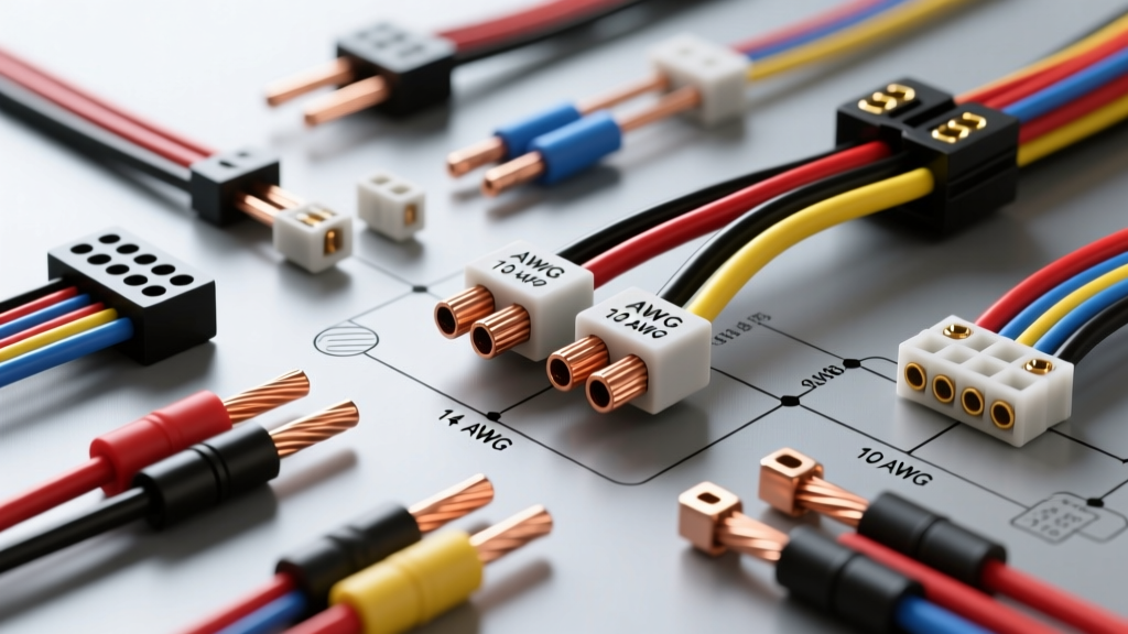
Understanding Automotive AWG Standards and SAE J1128
When designing, repairing, or modifying a vehicle electrical system, relying on residential electrical standards can lead to catastrophic failures, melted harnesses, or electrical fires. Automotive environments demand strict adherence to specific wire gauge amp ratings governed by the Society of Automotive Engineers (SAE). Unlike the National Electrical Code (NEC) used in household wiring, automotive primary wire is regulated under the SAE J1128 standard. This standard accounts for extreme temperature fluctuations, chemical exposure (oil, coolant, road salt), and continuous high-frequency vibration.
A critical distinction for automotive technicians is the difference between standard American Wire Gauge (AWG) and SAE metric sizing. While they are often used interchangeably in casual conversation, SAE wire sizes (measured in square millimeters, mm²) have slightly different copper cross-sectional areas compared to strict AWG specifications. For example, a standard 12 AWG wire has a cross-sectional area of 3.31 mm², whereas SAE 3.0 mm² wire is slightly thinner. Because of this, and the harsh under-hood environment, automotive wire gauge amp ratings must be derated compared to chassis wiring in open-air environments.
Comprehensive Automotive Wire Gauge Amp Ratings Chart
The following reference chart details the maximum current-carrying capacity (ampacity) for standard stranded copper automotive wire. These ratings assume a standard 12V to 14.4V DC system, an ambient temperature of 50°C (122°F), and wires routed in a standard engine bay harness.
| AWG Size | SAE Metric (mm²) | Max Amps (Chassis / Short Run) | Max Amps (Harness / Long Run) | Resistance (Ω per 1,000 ft) |
|---|---|---|---|---|
| 18 AWG | 0.80 mm² | 16 A | 10 A | 6.385 |
| 16 AWG | 1.30 mm² | 22 A | 13 A | 4.016 |
| 14 AWG | 2.00 mm² | 32 A | 15 A | 2.525 |
| 12 AWG | 3.00 mm² | 41 A | 20 A | 1.588 |
| 10 AWG | 5.00 mm² | 55 A | 30 A | 0.9989 |
| 8 AWG | 8.00 mm² | 73 A | 40 A | 0.6282 |
| 6 AWG | 13.0 mm² | 101 A | 55 A | 0.3951 |
| 4 AWG | 19.0 mm² | 124 A | 70 A | 0.2485 |
| 2 AWG | 32.0 mm² | 162 A | 95 A | 0.1563 |
| 1/0 AWG | 50.0 mm² | 210 A | 125 A | 0.0983 |
Note: 'Chassis' ratings apply to single wires in free air (e.g., a short battery ground strap). 'Harness' ratings apply to wires bundled together in a loom or conduit, where heat dissipation is restricted.
Voltage Drop Calculations for 12V and 24V Systems
Ampacity is only half the battle; voltage drop is the silent killer of automotive electrical performance. A wire might be thick enough not to melt, but if it is too long, the resistance will cause a significant voltage drop, starving components like fuel pumps, starter motors, and ECU sensors of necessary voltage. According to Painless Performance technical guidelines, a 12V circuit should never experience more than a 3% voltage drop (0.36V) under continuous load.
To calculate voltage drop (VD) in a DC circuit, use the following formula:
VD = (2 × L × R × I) / 1000
- L = One-way length of the wire in feet
- R = Resistance per 1,000 ft (from the chart above)
- I = Current draw in Amps
Real-World Example: You are wiring an electric winch solenoid in a Jeep Wrangler. The solenoid draws 300A and is located 10 feet from the battery. If you use 4 AWG wire (R = 0.2485), the calculation is: (2 × 10 × 0.2485 × 300) / 1000 = 1.49V drop. This leaves only 11.1V at the solenoid, which may cause the winch to stutter or fail under heavy load. Upgrading to 1/0 AWG wire (R = 0.0983) reduces the drop to 0.59V, ensuring reliable operation.
Application Guide: EFI Fuel Pump Wiring Upgrades
When swapping a high-flow aftermarket fuel pump (like a Walbro 450lph or DeatschTek DW400) into a classic GM LS or Ford Coyote engine, the OEM 14 AWG wiring is dangerously undersized. The OEM harness was designed for a 90-lph pump drawing roughly 8 amps. A 450-lph pump can draw 20+ amps at peak pressure, which will melt the factory harness or cause the ECU to see a lean condition due to low pump voltage.
The Proper Upgrade Protocol:
- Power Feed: Run a dedicated 10 AWG wire directly from the battery positive terminal, protected by a 40A MIDI or Mega fuse mounted within 7 inches of the battery.
- Relay Integration: Use a heavy-duty Bosch-style ISO Mini Relay. Connect the 10 AWG battery feed to Pin 30. Connect a 10 AWG wire from Pin 87 directly to the fuel pump positive terminal.
- Trigger Circuit: Splice into the OEM fuel pump trigger wire (typically Dark Green/White on GM, or Pink/White on Ford). Use 18 AWG wire to connect this signal to Pin 86 on the relay.
- Grounding: Connect Pin 85 to a clean, unpainted chassis ground using 18 AWG wire and a star-washer ring terminal.
By isolating the high-current path to 10 AWG wire, you ensure the pump receives a full 13.8V from the alternator, maximizing flow rate and preventing thermal degradation of the factory ECU harness.
High-Voltage EV Inverter Cables and Shielding
In modern electric vehicles (EVs), the wiring between the battery pack and the inverter requires massive current handling, often exceeding 400A during hard acceleration. These systems utilize 1/0 AWG to 4/0 AWG cables. However, standard copper wire is insufficient. EV high-voltage cables feature a distinctive bright orange cross-linked polyethylene (XLPE) insulation rated for 600V to 1000V DC.
Crucially, these thick cables incorporate a braided copper shielding layer to prevent Electromagnetic Interference (EMI) from disrupting the vehicle CAN bus networks. When terminating these cables to Amphenol or TE Connectivity HV connectors, technicians must use specialized hex-crimp dies and ensure the shielding braid is properly folded back and secured with a copper ferrule to maintain the Faraday cage effect.
Temperature Derating and Insulation Types
Ambient heat drastically reduces wire gauge amp ratings. The chart provided earlier assumes a 50°C ambient temperature. If you are routing wires near exhaust manifolds, turbochargers, or catalytic converters, local temperatures can easily exceed 125°C (257°F).
- GXL (General Cross-Linked): Standard OEM wire, rated to 125°C. Suitable for most cabin and general engine bay routing.
- TXL (Thin-wall Cross-Linked): Thinner insulation, same 125°C rating, used where weight and space are at a premium.
- SXL (Special Cross-Linked): Thicker insulation, rated to 150°C. Mandatory for routing near exhaust components.
- PTFE (Teflon): Rated up to 200°C+. Used in extreme motorsport applications, such as wiring inside the bell housing to a transmission-mounted speed sensor.
When routing 12 AWG GXL wire through an area where ambient temperatures reach 100°C, you must derate the ampacity by approximately 20%. A wire normally rated for 20A should be treated as a 16A wire to prevent insulation meltdown.
Diagnostic Testing: Troubleshooting Undersized Wiring
If a vehicle exhibits dimming headlights, slow cranking, or intermittent ECU resets, the wiring may be undersized or suffering from high-resistance corrosion. Do not rely on a standard resistance test (Ω) with the circuit powered off; a single strand of copper can show 0.1 ohms on a multimeter but will instantly bottleneck under a 50A load.
Instead, perform a Voltage Drop Test under load using a high-impedance digital multimeter (such as a Fluke 87V) set to Millivolts DC (mV DC).
- Activate the circuit (e.g., turn on the high-beam headlights or engage the starter).
- Place the red multimeter probe on the battery positive post and the black probe on the component's positive terminal.
- Read the voltage drop. A healthy 12 AWG power feed should show less than 0.20V (200mV) drop.
- Repeat on the ground side: Red probe on the component housing, black probe on the battery negative post. Ground drops should be less than 0.10V (100mV).
If your readings exceed these thresholds, the wire gauge is insufficient for the current draw, or the crimp terminals (such as Deutsch DT or Metripack 280 connectors) are suffering from internal fretting corrosion. Always use a ratcheting crimp tool with the correct die cavity to ensure a gas-tight connection, which prevents oxygen from entering the crimp barrel and causing resistance over time.
For further technical specifications on relay load management and terminal crimping standards, refer to the Bosch Automotive Relays documentation. Properly matching your wire gauge amp ratings to the specific thermal and electrical demands of the vehicle is the hallmark of professional automotive electrical engineering.