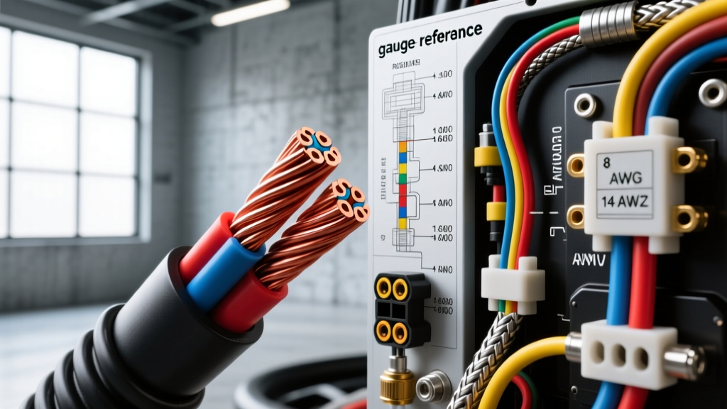
The Anatomy of Automotive Wire Gauge Markings
When executing a high-draw automotive modification—whether you are installing a 12,000-lb winch, a 2,000-watt mobile audio amplifier, or a heavy-duty onboard air compressor—understanding how to read wire gauge is the difference between a reliable system and an electrical fire. Many enthusiasts mistakenly rely on the physical thickness of the wire's outer jacket to determine its current-carrying capacity. However, jacket thickness is dictated by insulation requirements, not the copper cross-section. To properly size your wiring, you must decode the印字 (printing) on the jacket and understand the underlying American Wire Gauge (AWG) standards.
Decoding the Jacket Print: SAE vs. ISO Standards
High-quality automotive primary wire will feature a continuous printed string along its insulation jacket. According to the SAE International J1128 standard for low-tension primary cables, this print must include the manufacturer, the gauge size, the insulation type, and the temperature rating. Here is how to read the critical components of a standard jacket print, such as 10 AWG TXL SAE J1128 125°C:
- 10 AWG: This is the American Wire Gauge size. Remember the inverse rule: the lower the number, the thicker the copper core and the higher the ampacity. A 10 AWG wire has a cross-sectional area of approximately 5.26 mm².
- TXL (Thin Wall): This denotes the insulation thickness and material. TXL (Thin), GXL (General), and SXL (Standard) are cross-linked polyethylene (XLPE) insulations. TXL is the preferred choice for aftermarket harnesses because its thin wall allows for tighter routing in modern, cramped engine bays while resisting high temperatures and chemical exposure.
- SAE J1128: This confirms the wire meets the Society of Automotive Engineers' stringent physical, electrical, and thermal requirements for surface vehicle electrical systems.
- 125°C: The maximum continuous operating temperature of the insulation. For high-draw upgrades near exhaust manifolds or turbochargers, never use standard PVC wire (typically rated for 85°C to 105°C); always opt for XLPE-rated wire.
AWG vs. Metric: Cross-Sectional Area Comparison
While North American modders primarily use AWG, many imported vehicles (like European models or Japanese EVs) and high-end aftermarket audio kits use metric sizing (mm²). Knowing how to read wire gauge across both systems is crucial when splicing into factory harnesses or terminating international components. Below is a reference chart for common upgrade gauges:
| AWG Size | Metric (mm²) | Strand Count (Typical) | Max Ampacity (Chassis Wiring)* | Common Upgrade Application |
|---|---|---|---|---|
| 1/0 AWG | 53.5 mm² | 4,180 | 250A - 300A | Winch power, EV battery cables |
| 4 AWG | 21.1 mm² | 1,666 | 150A - 200A | Main audio power, high-output alternator feeds |
| 8 AWG | 8.36 mm² | 665 | 80A - 100A | Onboard air compressors, secondary battery isolators |
| 12 AWG | 3.31 mm² | 264 | 30A - 40A | Off-road LED light bars, fuel pumps |
| 14 AWG | 2.08 mm² | 168 | 20A - 25A | Relay trigger circuits, interior accessory feeds |
*Note: Ampacity ratings are based on single wires in free air at an ambient temperature of 30°C. Bundling wires or routing them through high-heat zones requires derating. Always consult the Mad Electrical automotive ampacity charts for precise derating formulas.
The Copper Core: Reading OFC vs. CCA
Reading the wire gauge is only half the battle; you must also read the material composition. The aftermarket is flooded with Copper-Clad Aluminum (CCA) wire. CCA features an aluminum core coated in a thin layer of copper. Because aluminum has roughly 61% of the conductivity of copper, a 4 AWG CCA wire will perform closer to an 8 AWG Oxygen-Free Copper (OFC) wire, leading to severe voltage drop and overheating under high-draw conditions.
How to Inspect the Core
To verify your wire, use a flush cutter to snip the end of the cable. Examine the cross-section under a bright light. If the center of the strands appears silvery or white, you have CCA. True OFC will be uniformly copper-colored all the way through. For any upgrade drawing over 50 amps continuously, OFC is non-negotiable.
Project-Specific Gauge Selection and Routing
Let us apply gauge reading to three common high-draw modification projects, detailing the specific wire sizes, fusing, and termination strategies required for a factory-grade installation.
Project 1: 12,000-lb Front-Mount Winch
A 12,000-lb winch can pull upwards of 400 to 500 amps under maximum stall load. While the continuous draw is lower, the cabling must handle peak surges without melting the insulation.
- Wire Gauge: 1/0 AWG OFC (or 2/0 AWG for runs exceeding 8 feet total).
- Insulation: SXL or battery cable (SGX) for maximum abrasion resistance against the chassis.
- Termination: Anderson Powerpole SB175 connector. This allows for quick disconnects if the winch needs to be removed. Crimp the 1/0 AWG wire using a heavy-duty hex-crimp tool, and seal the barrel entry point with adhesive-lined dual-wall heat shrink.
- Protection: Install a 250A ANL fuse within 12 inches of the positive battery terminal.
Project 2: 400W Off-Road LED Light Bar
A 400W light bar on a 14.4V system draws approximately 27.7 amps. Because the wiring must run from the engine bay to the roof rack or front bumper, length becomes a critical factor.
- Wire Gauge: 10 AWG TXL for the main power and ground runs to compensate for voltage drop over distance.
- Switching Circuit: 14 AWG TXL from the relay trigger to the interior switch.
- Termination: Use TE Connectivity Deutsch DT series 2-pin connectors at the light bar connection. The DT connector handles up to 13A per pin, so for a 28A draw, you must use two pins paralleled for power and two for ground, or step up to a 4-pin Deutsch DTM connector rated for higher aggregate current. Always insert the silicone wedgelock after seating the pins to prevent vibration-induced back-outs.
Project 3: High-Output Alternator Upgrade (250A+)
Upgrading to a 250A alternator to support auxiliary lighting and audio requires replacing the factory charge wire, which is typically only rated for 120A-150A (usually 6 AWG or 8 AWG).
- Wire Gauge: 1/0 AWG OFC welding cable. Welding cable features ultra-fine stranding (over 4,000 strands), making it incredibly flexible for routing around tight engine accessories and steering shafts.
- Termination: Heavy-duty copper ring terminals crimped and soldered, or sealed with marine-grade heat shrink to prevent battery acid corrosion.
- Fusing: A 300A Class-T or Mega fuse mounted directly on the alternator output stud or within inches of the battery positive.
Calculating Voltage Drop in Long Harness Runs
Reading the gauge on the jacket does not account for the distance the current must travel. Voltage drop occurs when wire resistance dissipates electrical energy as heat over long distances. If you are wiring a rear-mounted air compressor or a trailer charge line, a 10 AWG wire might be perfectly safe for a 3-foot run, but completely inadequate for a 20-foot run.
Use the following formula to calculate voltage drop:
VD = (2 x L x I x R) / 1000
- VD: Voltage Drop
- L: Length of the wire in feet (multiplied by 2 to account for the positive and negative ground return path)
- I: Current draw in Amps
- R: Resistance per 1,000 feet of the specific AWG wire at operating temperature
Real-World Example: You are wiring a rear-mounted 30A compressor using 12 AWG wire (Resistance = 1.588 ohms per 1,000 ft). The run is 15 feet from the battery.
VD = (2 x 15 x 30 x 1.588) / 1000 = 1.42 Volts.
A 1.42V drop on a 14.4V system leaves only 12.98V at the compressor. While this is generally acceptable for a motor, sensitive electronics and ECU modules require a voltage drop of less than 0.5V. In those cases, you must step up to a thicker gauge, such as 8 AWG, regardless of the basic ampacity chart.
Matching Terminals to Your Wire Gauge
An accurately read wire gauge is useless if paired with the wrong terminal. A common failure mode in aftermarket wiring is using a universal crimp terminal that is too large, leading the installer to fold the wire over to fill the barrel. This creates a high-resistance point that will melt under load.
- Heat Shrink Terminals: Color-coded by gauge. Red = 18-22 AWG, Blue = 14-16 AWG, Yellow = 10-12 AWG. Always use a ratcheting crimp tool designed for insulated terminals to ensure the metal barrel is crushed around the copper, while the heat shrink seals the insulation.
- Open Barrel (Stamping) Terminals: Used in factory Metri-Pack and Weather-Pack connectors. These require a specific non-insulated crimp die. The wire brush crimp (the smaller section) bites the bare copper, while the insulation crimp (the larger section) grips the wire jacket to provide strain relief.
Summary for the Automotive Modder
Mastering how to read wire gauge involves looking past the outer jacket. By verifying the AWG or metric cross-section, confirming the XLPE insulation rating, and ensuring the core is pure OFC, you guarantee that your high-draw upgrades will perform safely under the most demanding off-road or competition conditions. Always cross-reference your physical wire measurements with SAE ampacity standards and account for voltage drop on extended runs to build a harness that rivals factory engineering.