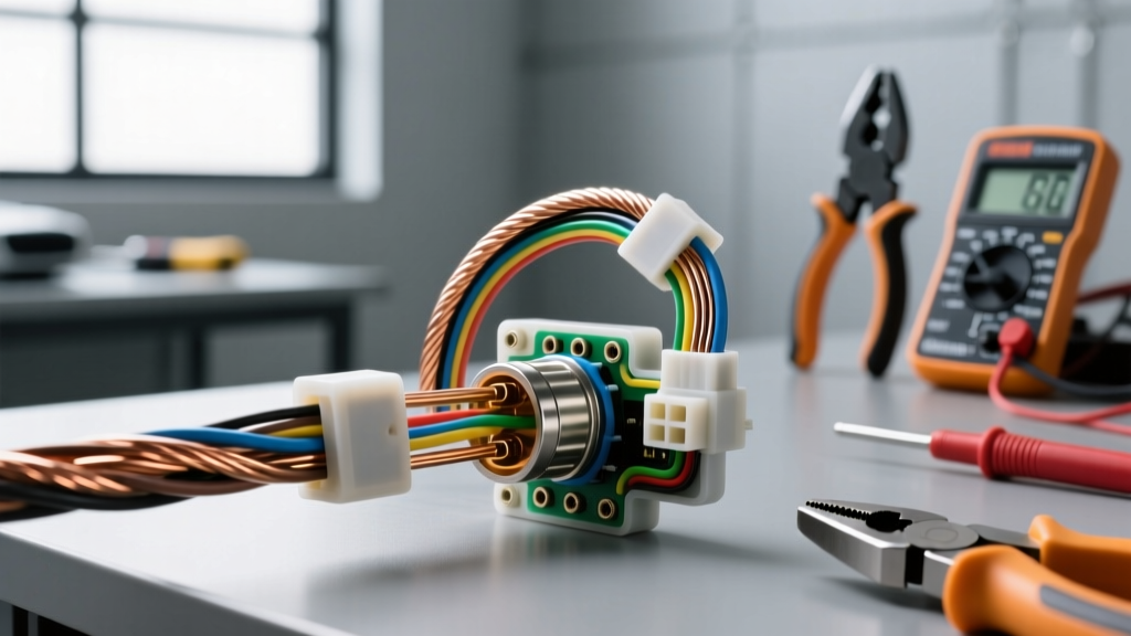
The Nervous System of Modern Vehicles: Understanding .5mm Wire Gauge
When beginners dive into automotive electrical work, they usually focus on the heavy hitters: 4-AWG battery cables, 10-AWG amplifier power feeds, or 12-AWG headlight circuits. However, the true complexity and reliability of a modern vehicle rely on its 'nervous system'—the low-current sensor and data networks. At the heart of these micro-circuits is the .5mm wire gauge (properly designated as 0.5mm²). Whether you are diagnosing a check engine light, installing a wideband O2 sensor, or repairing a CAN bus network, mastering the fundamentals of this specific wire size is non-negotiable for professional-grade results.
Metric Sizing vs. AWG: What Does 0.5mm² Actually Mean?
One of the most common points of confusion for those transitioning from household electronics to automotive wiring is the shift from American Wire Gauge (AWG) to the metric system. Under international standards like SAE J1128 and ISO 6722, automotive wire is sized by its cross-sectional area in square millimeters, not by a gauge number based on drawing dies.
A .5mm wire gauge refers to a conductor with a total cross-sectional area of 0.5 square millimeters. In the AWG system, 0.5mm² is the direct equivalent of 20 AWG stranded wire. Unlike solid core wire used in residential walls, automotive 0.5mm² wire is highly stranded—typically consisting of 19 strands of 0.18mm copper or 32 strands of 0.15mm copper. This high strand count provides the extreme flexibility required to withstand the constant vibrations, thermal expansion, and physical movement found in engine bays and door hinges.
Technical Specifications and Ampacity Chart
Before tapping into any circuit, you must understand the physical and electrical limits of the wire. Below is the standard specification chart for 0.5mm² automotive primary wire (such as those found in the TE Connectivity Automotive Wire Catalog).
| Specification | Metric (0.5mm²) | AWG Equivalent (20 AWG) |
|---|---|---|
| Cross-Sectional Area | 0.50 mm² | 0.518 mm² |
| Typical Stranding | 19 / 0.18 mm | 19 / 0.0127 in |
| Nominal Insulation OD | 1.40 mm - 1.70 mm | 0.055 in - 0.067 in |
| Resistance at 20°C | 37.1 Ω / km (max) | 10.3 Ω / 1000 ft |
| Max Ampacity (Free Air) | 9 - 11 Amps | 11 Amps |
| Max Ampacity (Bundled Harness) | 4 - 5 Amps | 5 Amps |
Expert Note on Ampacity: While 0.5mm² wire can technically handle up to 11 amps in free air, it is almost never used for high-draw loads in vehicles. When bundled inside a harness wrapped in Tesa tape and subjected to 100°C+ engine bay temperatures, its current-carrying capacity drops significantly. Therefore, 0.5mm² is strictly reserved for low-current signal, data, and reference voltage circuits.
Common Automotive Applications for .5mm Wire Gauge
Where will you actually encounter this thin wire in a vehicle? Here are the three most critical systems that rely on 0.5mm² conductors.
1. Oxygen (O2) Sensor Signal Circuits
O2 sensors require highly accurate voltage readings to adjust fuel trims. A standard narrowband O2 sensor generates a signal between 0.1V (lean) and 0.9V (rich). Because the Powertrain Control Module (PCM) measures this voltage using high-impedance inputs, even a fraction of an ohm of added resistance can skew the reading. Automakers use 0.5mm² wire for the signal and signal-ground circuits to minimize voltage drop while maintaining harness flexibility.
- Typical GM LS1 4-Wire O2 Pinout: Pin A (Black) - Signal Ground (0.5mm²), Pin B (Purple) - Signal (0.5mm²), Pin C (Pink) - Heater 12V (0.8mm²), Pin D (Black/White) - Heater Ground (0.8mm²).
- Typical Bosch 4-Wire O2 Pinout: Black (Signal), Grey (Signal Ground), White (Heater), White (Heater).
2. CAN Bus Data Networks
The Controller Area Network (CAN) is the backbone of modern vehicle communication. CAN High (CAN-H) and CAN Low (CAN-L) lines operate on a differential voltage system to reject electromagnetic interference (EMI). These wires are almost universally 0.5mm² (or sometimes 0.35mm² for high-speed networks) and are twisted together at a precise rate—usually one twist every 25mm to 50mm. This twisting is critical for canceling out common-mode noise from alternators and ignition coils.
3. Mass Air Flow (MAF) and MAP Sensors
The 5-Volt Reference (5V REF) and Signal Return circuits for MAF, MAP, and Throttle Position Sensors (TPS) frequently utilize 0.5mm² wire. These circuits draw less than 100 milliamps, making the thin gauge perfectly adequate while saving weight and space in the ECU connector.
Beginner Mistakes: Stripping and Crimping Thin-Gauge Wire
Working with .5mm wire gauge requires a delicate touch. The most common beginner mistake is using heavy-duty, hardware-store wire strippers that crush or nick the 19 microscopic copper strands. If you sever even a few strands, you reduce the cross-sectional area, creating a localized hot spot and increasing resistance.
The Right Tools for the Job
Invest in precision automatic wire strippers with micro-adjustment screws, or use dedicated flush-cut strippers designed specifically for 20-24 AWG wire. When stripping the thin PVC or cross-linked polyethylene (XLPE) insulation, pull straight off; never twist the wire, as the thin strands will bind and snap.
Open Barrel vs. Closed Barrel Terminals
For 0.5mm² wire, open-barrel (F-crimp) terminals are the industry standard, particularly for Deutsch, Bosch, and Delphi connectors. An open-barrel crimp features two distinct crimp zones:
- The Conductor Crimp: The inner 'F' shaped wings fold over the bare copper strands in a precise interlocking fold, creating a gas-tight connection that prevents oxidation.
- The Insulation Crimp: The outer, larger wings wrap around the wire jacket to provide strain relief, ensuring that any pulling force is absorbed by the insulation, not the delicate copper strands.
Ensure your crimping tool has a dedicated 0.25-0.5mm² die. Using a larger 1.0mm² die will result in a loose crimp that will inevitably vibrate apart or cause a high-resistance voltage drop.
The Solder vs. Crimp Debate in Engine Bays
Many beginners default to soldering thin wires, assuming it creates a stronger bond. In automotive applications, especially under the hood, soldering 0.5mm² wire is strongly discouraged. Solder wicks into the strands via capillary action, creating a rigid, brittle section of wire right at the edge of the insulation. In an engine bay subjected to constant vibration, this stiff transition point becomes a fulcrum, causing the copper strands to fatigue and snap. Furthermore, if acid-core flux is not perfectly cleaned, it will cause galvanic corrosion, turning the copper green and destroying the signal. Always use a proper mechanical crimp followed by dual-wall, adhesive-lined heat shrink to seal out moisture.
Troubleshooting Signal Loss and Voltage Drop
Because .5mm wire gauge is used for highly sensitive analog and digital signals, minor physical damage leads to major drivability issues. According to resources like AutoShop 101 Electrical Fundamentals, understanding voltage drop is key to diagnosing thin-gauge circuits.
Scenario: The Phantom P0102 Code
A vehicle throws a P0102 (Mass Air Flow Circuit Low Voltage) code. The beginner replaces the MAF sensor, but the code returns. The expert checks the 0.5mm² Signal Ground wire. By performing a voltage drop test across the ground wire with the key on, engine running, the expert discovers a 0.4V drop. The PCM expects a 0.0V ground reference; the 0.4V drop artificially lowers the 5V signal return, tricking the PCM into reading a 'low flow' condition. The culprit? A corroded splice pack where the 0.5mm² MAF ground shares a node with the MAP sensor ground. Repairing the splice with a proper step-crimp and sealing it resolves the issue without throwing parts at the car.
CAN Bus Repair Rules
If you must repair a broken 0.5mm² CAN bus wire, never untwist the pair more than 50mm (2 inches) from the point of the break. Untwisting the wire destroys the electromagnetic cancellation effect, leading to localized EMI vulnerability, network dropouts, and U-codes (communication network fault codes). Always stagger your solder sleeves or crimps on CAN-H and CAN-L so the bulky repair joints do not sit side-by-side, which would alter the impedance of the twisted pair.
Summary
Mastering the .5mm wire gauge is a rite of passage for automotive electricians. By respecting its ampacity limits, utilizing the correct micro-crimping tools, and understanding its critical role in sensor and data networks, you elevate your work from amateur splices to OEM-level reliability. Always prioritize gas-tight crimps, proper strain relief, and meticulous attention to wire color codes and pinouts when working with the vehicle's most delicate circuits.