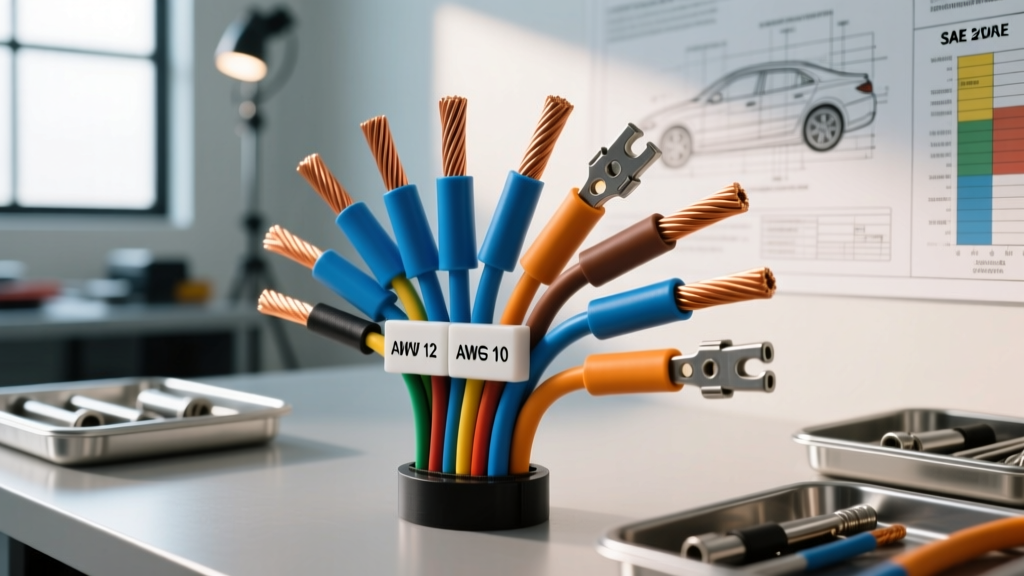
The Baseline: AWG Sizing for 20-Amp Automotive Circuits
When designing, upgrading, or troubleshooting high-current automotive circuits, determining the correct 20a wire gauge is a critical engineering decision. A 20-amp continuous load represents a significant threshold in vehicle electrical systems, typically encompassing high-flow EFI fuel pumps, PWM-controlled cooling fans, ECU main power feeds, and heavy-duty lighting arrays. While basic electrical heuristics often point to 12 AWG as the default for 20 amps, automotive environments demand a much more rigorous approach to ampacity, voltage drop, and thermal management.
In a standard 14.0-volt charging system, a 20A continuous load draws 280 watts of power. If the wire gauge is undersized, the resulting resistance generates excess heat, degrading the insulation and potentially causing a thermal runaway event. Conversely, oversized wire adds unnecessary weight, increases harness stiffness, and complicates terminal crimping. This guide provides an advanced technical deep dive into the specifications, derating factors, and real-world applications for selecting the optimal wire gauge for 20A automotive circuits.
SAE J1128 vs. NEC: The Chassis Wiring Distinction
A common mistake among novice builders is applying National Electrical Code (NEC) standards to automotive chassis wiring. The NEC dictates that 12 AWG copper wire is rated for 20 amps in residential branch circuits. However, automotive wiring is governed by the Society of Automotive Engineers (SAE), specifically the SAE J1128 Low Tension Primary Cable Standard. SAE standards account for the harsh under-hood environment, where ambient temperatures routinely exceed 100°C near exhaust manifolds and turbocharger housings.
Furthermore, SAE J1128 ampacity ratings assume a single wire routed in free air. In a vehicle, wires are bundled into corrugated looms or wrapped in Tesa tape harnesses. Wire bundling severely restricts convective cooling, requiring strict thermal derating:
- Single Wire in Free Air: 12 AWG TXL is safely rated for ~25A continuous at 125°C ambient.
- Bundle of 3-6 Wires: Derate ampacity by 20%. A 12 AWG wire in a 6-wire harness is effectively limited to ~20A.
- Bundle of 7-24 Wires: Derate ampacity by 30-40%. A 12 AWG wire in a main body harness may only safely carry 15A, necessitating an upgrade to 10 AWG for a 20A load.
Therefore, while 12 AWG is the absolute minimum for a 20A circuit in free air, 10 AWG (5.26 mm² cross-sectional area) is the recommended baseline for 20A loads routed through dense engine bay harnesses or enclosed firewall grommets.
Voltage Drop Analysis for 20A Continuous Loads
Ampacity is only half of the wire gauge equation; voltage drop is equally critical. Modern ECUs, sensors, and PWM controllers require stable voltage. A voltage drop exceeding 3% (0.42V on a 14.0V system) can cause erratic fuel pump speeds, ECU reset loops, or improper solenoid actuation. The formula for voltage drop in a DC circuit is:
VD = (2 × L × I × R) / 1000
Where L = one-way length in feet, I = current (20A), and R = resistance per 1000 ft of wire.
| Wire Gauge (AWG) | Cross-Section (mm²) | Resistance (Ω/1000ft) | Voltage Drop @ 5 ft (20A) | Voltage Drop @ 15 ft (20A) | Max Recommended Run (20A) |
|---|---|---|---|---|---|
| 14 AWG | 2.08 | 2.525 | 0.50V (3.6%) | 1.51V (10.8%) | 3 ft (Not Recommended) |
| 12 AWG | 3.31 | 1.588 | 0.32V (2.3%) | 0.95V (6.8%) | 10 ft (Free Air Only) |
| 10 AWG | 5.26 | 0.998 | 0.20V (1.4%) | 0.60V (4.3%) | 18 ft (Harness Safe) |
| 8 AWG | 8.37 | 0.628 | 0.13V (0.9%) | 0.38V (2.7%) | 30+ ft (Heavy Duty) |
As the data illustrates, routing a 12 AWG wire 15 feet from the battery to a rear-mounted fuel pump yields nearly a 1-volt drop, starving the pump of necessary voltage. For any 20A load located in the trunk or rear of a long-wheelbase vehicle, 10 AWG or 8 AWG must be utilized to maintain system efficiency.
Insulation Selection: TXL, GXL, and SXL Specifications
Once the copper cross-section is determined, the insulation type must be matched to the physical routing environment. Standard PVC-insulated wire (like THHN or standard trailer wire) is entirely unsuitable for under-hood 20A circuits due to its low melting point and poor abrasion resistance. Automotive primary wire utilizes Cross-Linked Polyethylene (XLPE), which provides superior thermal and chemical resistance.
- TXL (Thin-Wall): Features a 0.016-inch wall thickness. It is lightweight and highly flexible, making it ideal for interior cabin routing or tight harness wraps. Rated for 125°C continuous.
- GXL (General-Wall): Features a 0.023-inch wall thickness. This is the OEM standard for most engine bay harnesses, offering a balance of flexibility and mechanical protection against sharp metal edges.
- SXL (Standard-Wall): Features a 0.033-inch wall thickness and a 150°C rating. SXL is mandatory for 20A circuits routed within 6 inches of exhaust headers, turbocharger downpipes, or EGR tubing.
Connector Compatibility for 20A Feeds
A 10 AWG or 12 AWG wire is useless if the terminal and connector housing cannot handle 20 amps without melting. The Aptiv Metri-Pack 280 Series is the industry standard for 20A automotive connections. The '280' designation refers to the 2.8mm male blade width, which is rated for up to 22 amps continuous when properly crimped and seated.
For environments requiring high moisture ingress protection (IP69K), the TE Connectivity Deutsch DT Series is frequently specified. However, standard Deutsch DT contacts are rated for 13 amps per pin. To safely pass a 20A continuous load through a Deutsch connector, engineers must either use the larger DTP series (rated for 25A) or parallel two DT pins together. Never rely on a single standard DT pin for a 20A fuel pump or fan circuit, as the pin will overheat and back out of the housing.
Application Case Studies: Real-World 20A Wiring
Case Study 1: High-Flow EFI Fuel Pumps (Walbro 255 / Bosch 044)
Upgrading to a high-flow inline or in-tank fuel pump is a common modification. A Walbro 255 LPH pump draws approximately 12-14 amps at 43 PSI, but inrush current upon startup and current draw at higher pressures (60+ PSI) can easily spike to 18-20 amps. OEM fuel pump relays and 14 AWG wiring will overheat under these conditions.
The Fix: Run a dedicated 12 AWG TXL power feed directly from the battery positive terminal via a 30A ATO fuse and a heavy-duty Bosch-style 5-pin relay. Use a Metri-Pack 280 pigtail at the pump connection. Ensure the ground path utilizes an equal 12 AWG wire bolted to bare chassis metal with a star washer, applying anti-corrosion dielectric grease to the ring terminal.
Case Study 2: LS-Swap ECU Main Power Feeds
When performing an LS V8 swap, the ECU requires robust, low-resistance power to function correctly. On the GM LS1/LS6 PCM (C1 Black connector), Pins 20 and 57 serve as the main switched 12V+ feeds. These pins power the internal injector and coil drivers, which can collectively draw upwards of 20 amps during high-RPM, high-duty-cycle operation.
The Fix: Utilize 12 AWG GXL wire for Pins 20 and 57. Because the C1 connector uses Metri-Pack 150 series terminals for these specific pins, which are not rated for 20A individually, GM engineers designed the system to share the load across both pins. You must ensure both pins are populated with 12 AWG wire and fed from the same ignition-switched relay source to balance the current draw and prevent PCM internal trace damage.
Terminal Crimping Specifications
For 12 AWG and 10 AWG wire, achieving a proper cold-weld crimp is non-negotiable. A poorly crimped terminal introduces micro-ohms of resistance, which at 20 amps generates localized heat. When using open-barrel terminals (like Metri-Pack or Weather-Pack), the crimp height for 12 AWG wire should be precisely 0.065 inches, measured with a digital caliper. The insulation crimp should securely grip the wire jacket without piercing it. Always perform a pull-test; a correctly crimped 12 AWG terminal should withstand a minimum pull-out force of 60 lbs before the wire yields.