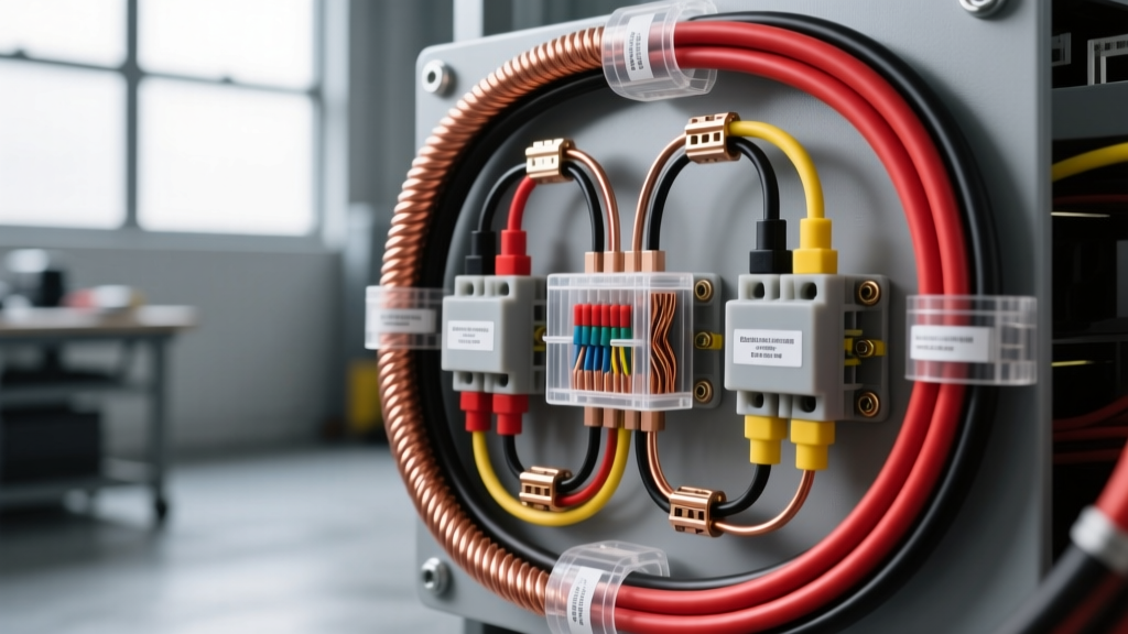
The Hidden Dangers of Oversizing Fuel Pump Wiring
When upgrading to high-flow aftermarket fuel pumps (such as the Walbro 450, DeatschWerks DW300, or dual-pump configurations), enthusiasts frequently jump straight to 10 AWG wire to eliminate voltage drop over long chassis runs. While using 10 gauge wire for fuel pump applications offers excellent conductivity (5.26 mm² cross-section, approximately 1.0 mΩ/ft), simply throwing thicker wire at the electrical system introduces severe safety hazards if the supporting circuit components are not properly matched. Automotive electrical fires frequently originate not from undersized wire, but from mismatched fusing, improper terminal crimps, and ignored ground circuits. Below, we break down the most critical mistakes made when installing 10 AWG fuel pump harnesses and how to engineer a safe, reliable circuit.
Mistake #1: Fusing for Wire Ampacity Instead of Component Load
The most dangerous mistake in aftermarket fuel pump wiring is selecting a fuse based on the wire's maximum ampacity rather than the component's operational draw. According to the SAE J1128 standard, 10 AWG TXL (cross-linked polyethylene) wire can safely handle 30 to 40 amps in a typical chassis wiring bundle. Consequently, many installers place a 30A or 40A fuse at the battery to 'protect the wire'.
The Safety Warning: A high-flow fuel pump typically draws between 12A and 18A at operating pressure. If the pump impeller seizes or the commutator shorts internally, the stall current may spike to 25A. A 30A or 40A fuse will not blow under these conditions. Instead, the pump housing will overheat, melt the surrounding plastic fuel flange, and potentially ignite fuel vapors. Rule of thumb: The fuse must protect the weakest link in the circuit, which is the fuel pump itself. Always use a fuse rated 120% to 150% of the pump's maximum continuous draw (e.g., a 20A or 25A ATO/Mini fuse for an 18A pump), regardless of the 10 AWG wire's capacity.
Mistake #2: Forcing 10 AWG into Metri-Pack 150/280 Connectors
OEM fuel pump flanges and tank-side pigtails almost universally utilize Delphi (now Aptiv) Metri-Pack 150 or 280 series sealed connectors. The standard Metri-Pack 150 terminal is designed for 14 to 18 AWG wire. The Metri-Pack 280 series maxes out at 12 AWG in most standard automotive applications.
Installers often attempt to strip back the thick 10 AWG insulation, fold the bare copper strands, and force them into a 12 AWG crimp terminal, or worse, solder them directly to the OEM pigtail and wrap it in electrical tape. This creates a massive point of high resistance. Under the constant vibration of the vehicle chassis, this sloppy connection suffers from fretting corrosion, leading to localized heating, voltage drop, and eventually a melted connector housing.
The Fix: Use a sealed transition pigtail. Run the 10 AWG wire from the relay to a sealed junction box or a dual-wall adhesive heat-shrink transition point near the fuel tank. Step down to a proper 12 AWG SAE J1128 GXL wire for the final 18 inches into the tank, utilizing the correct Aptiv Metri-Pack 280 female terminal (Part #12015791 or equivalent) and a ratcheting crimper to ensure a gas-tight, factory-spec connection.
Mistake #3: Ignoring the OEM Ground Circuit Bottleneck
Upgrading the power feed to 10 AWG while leaving the factory 16 AWG ground wire intact is a classic bottleneck error. Voltage drop occurs on both the positive and negative sides of the circuit. If your 10 AWG power wire drops only 0.1V, but the OEM 16 AWG ground wire drops 1.2V due to its higher resistance (4.02 mΩ/ft), your fuel pump is still being starved of voltage.
Furthermore, pushing 18+ amps through a factory 16 AWG ground wire and a small M6 chassis grounding stud will cause the ground point to overheat. This can melt the insulation, cause galvanic corrosion against the chassis, and trigger erratic ECU behavior if the fuel pump ground is shared with fuel tank pressure sensors.
The Fix: You must upgrade the ground wire to match the power wire (or at minimum, use 12 AWG). Run a dedicated 10 AWG or 12 AWG ground wire from the fuel pump flange transition directly to a clean, bare-metal chassis point. Use an M8 or M10 stainless steel ring terminal, secure it with a flange nut, and torque it to 10-12 Nm. Coat the terminal in dielectric grease to prevent moisture intrusion.
Mistake #4: Using CCA Wire in High-Vibration Environments
To save money, many online retailers sell '10 AWG' wire that is actually Copper Clad Aluminum (CCA). CCA wire has a higher electrical resistance than pure Oxygen-Free Copper (OFC) and is significantly more brittle. In the harsh, high-vibration environment underneath a vehicle, CCA wire work-hardens, snaps, and fractures inside the insulation. When exposed to road salt and moisture, the aluminum core undergoes rapid galvanic corrosion, turning into a white, non-conductive powder inside the crimp terminal.
The Fix: Only purchase wire that explicitly certifies compliance with automotive wiring standards and SAE J1128 (TXL, GXL, or SXL). These specifications guarantee pure copper conductors with cross-linked insulation capable of withstanding 125°C to 150°C temperatures and harsh chemical exposure (gasoline, oil, road salt).
10 AWG Fuel Pump Wiring Specification & Comparison Chart
| Wire Gauge (AWG) | Cross-Section (mm²) | Resistance (Ω/1000ft) | Max Chassis Amps (SAE J1128) | Ideal Fuel Pump Application | Recommended Max Fuse |
|---|---|---|---|---|---|
| 14 AWG | 2.08 | 2.52 | 15A | OEM Pumps (Short runs, < 12A draw) | 15A |
| 12 AWG | 3.31 | 1.59 | 20A | Stage 1 Upgrades (Walbro 255, 14A draw) | 20A |
| 10 AWG (OFC) | 5.26 | 1.00 | 30A - 40A | High-Flow / Dual Pumps (18A - 25A draw, long runs) | 25A - 30A (Load Dependent) |
| 8 AWG | 8.37 | 0.63 | 50A | Race Fuel Cells / Brushless Pump Controllers | 40A+ |
Safe 10 AWG Relay Harness Architecture (Step-by-Step)
To safely integrate 10 gauge wire for fuel pump setups without overloading the factory ECU driver or fuel pump relay, you must build a dedicated bypass harness using a heavy-duty Bosch-style ISO mini relay. Follow this pinout architecture:
- Pin 30 (Power In): Run 10 AWG OFC wire directly from the battery positive terminal. Install a 25A or 30A Mega-Fuse or ANL fuse within 8 inches of the battery terminal. Crimp using a closed-end 10 AWG ring terminal and torque to battery spec.
- Pin 87 (Power Out to Pump): Run 10 AWG wire from the relay to the rear of the vehicle. Protect the wire with split-loom corrugated tubing and secure it every 12 inches with UV-resistant zip ties or P-clips.
- Pin 86 (Relay Coil Power): Tap into an ignition-switched 12V source (e.g., fuel pump control module output or IGN fuse) using a 16 AWG wire and a proper Posi-Tap or fuse-tap adapter.
- Pin 85 (Relay Coil Ground): Run 16 AWG wire to a clean local chassis ground.
Pro-Tip: Always install a flyback diode (e.g., 1N4001) across pins 85 and 86 (stripe facing Pin 86) if your vehicle's ECU directly triggers the relay. This prevents the inductive voltage spike from the relay coil collapsing from back-feeding and frying the ECU's internal fuel pump driver transistor.
Conclusion
Upgrading to 10 AWG wire is a highly effective way to ensure your high-performance fuel pump receives consistent voltage under heavy load, preventing lean conditions and engine damage. However, wire gauge is only one variable in the electrical equation. By respecting component-level fusing, executing proper connector step-downs, matching your ground circuit, and strictly using SAE-certified OFC wire, you ensure your fuel delivery system remains safe, reliable, and fire-free for the life of the vehicle.