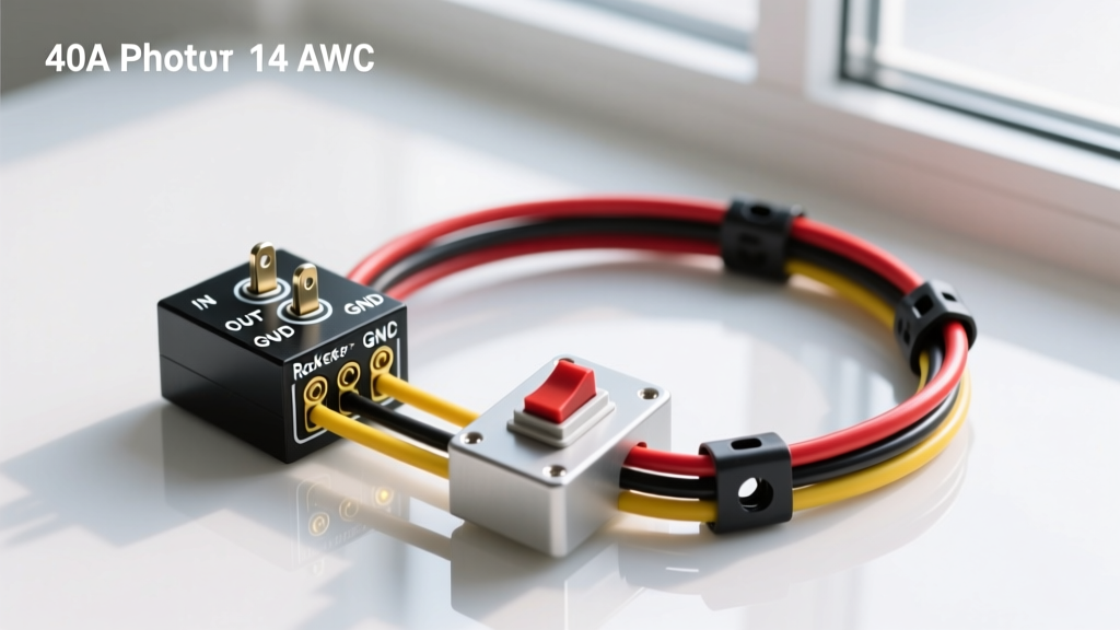
Understanding the 3-Pin Rocker Switch Architecture
Wiring auxiliary off-road lights, winch controls, or onboard air compressors requires a robust switching mechanism that isolates the high-amperage load from the vehicle's delicate dash wiring. The standard 3-pin SPST (Single Pole, Single Throw) rocker switch with an integrated illumination LED is the industry standard for these applications. However, running a 15-amp LED light bar directly through the switch contacts will cause internal arcing, voltage drop, and eventual switch failure. To install this correctly, you must use the rocker switch strictly as a low-amperage trigger for a high-amperage Bosch-style automotive relay.
According to Littelfuse technical specifications, the internal contacts of a standard marine-grade rocker switch are typically rated for 10A to 20A at 12V DC. Because auxiliary lighting circuits frequently draw near or above this threshold during startup surges, utilizing a relay harness is mandatory for long-term reliability and fire prevention.
Standard 3-Pin Rocker Switch Pinout
Before cutting any wire, you must identify the terminals on the back of the switch housing. While some manufacturers use printed numbers, others rely on terminal placement. Always verify with a multimeter set to the continuity/ohms setting.
| Pin Number | Function | Connection Target | Wire Color (Standard) |
|---|---|---|---|
| Pin 1 | Ground (Illumination) | Chassis Ground / Dash Ground | Black (18 AWG) |
| Pin 2 | 12V Accessory Source | Fused IGN/ACC Circuit (Radio/Cig Lighter) | Red (18 AWG) |
| Pin 3 | Load / Trigger Output | Relay Pin 86 (Coil Trigger) | Blue (18 AWG) |
Note: When the switch is in the OFF position, Pins 2 and 3 are disconnected. When flipped ON, Pin 2 bridges to Pin 3, sending 12V to the relay coil while simultaneously illuminating the internal LED (which grounds through Pin 1).
Required Materials and SAE Wire Specifications
Automotive environments subject wiring to extreme thermal cycling, vibration, and corrosive elements. Using household THHN wire or cheap CCA (Copper Clad Aluminum) wire will result in brittle insulation and severe voltage drop. You must use SAE-rated automotive primary wire.
As defined in the SAE J1128 Low Tension Primary Cable standard, GXL (General Cross-Linked) or TXL insulation is required for under-hood routing due to its 125°C temperature rating and thin-wall construction, which allows for easier routing through tight firewall grommets.
Bill of Materials (BOM)
- Wire: 18 AWG GXL (Red, Black, Blue) for the switch trigger circuit; 12 AWG GXL (Red, Black) for the main battery feed; 14 AWG GXL (Red) for the relay-to-light feed.
- Connectors: 1/4" fully insulated female quick-disconnect spades (for switch pins); 3/8" heat-shrink ring terminals (for battery and chassis grounds).
- Relay: Standard ISO Mini 4-Pin 12V 40A Relay (Bosch-style).
- Protection: Inline ATC fuse holder with appropriate amperage fuse (see calculation chart below); 3:1 adhesive-lined dual-wall heat shrink tubing.
- Tools: Ratcheting wire crimp tool (specifically for open-barrel and closed-barrel terminals), wire strippers, heat gun, multimeter.
Step-by-Step Installation Guide
Step 1: Prep and Crimp the Switch Pigtails
Cut three 12-inch lengths of 18 AWG wire (Red, Blue, Black). Strip exactly 3/16" of insulation from one end of each wire. Slide a piece of 3:1 adhesive-lined heat shrink onto the wire before crimping. Insert the bare copper into the 1/4" female spade terminal's wire barrel. Using a ratcheting crimper, crush the wire barrel tightly. Next, crimp the insulation barrel over the wire jacket. This dual-crimp prevents the wire from pivoting and fatiguing at the copper joint. Slide the heat shrink over the terminal junction and apply heat until the adhesive bleeds out the ends, creating a waterproof seal.
Step 2: Route the Trigger Wires Through the Firewall
Push the Red, Blue, and Black wires through an existing rubber firewall grommet. Never pierce a virgin rubber grommet with bare wire, as the sharp edge will eventually slice the insulation and cause a dead short. Use a plastic trim removal tool to gently coax the wires alongside the existing factory harness. Secure the wires with Tesa tape (fleece automotive wiring tape) to prevent rattling against the dash framework.
Step 3: Tap the 12V Accessory Source (Pin 2)
Locate a 12V accessory circuit that only powers on when the ignition is in the ACC or ON position (e.g., the rear wiper circuit, radio harness, or cigarette lighter feed). Use a T-tap or, preferably, cut the factory wire and use a solder-seal butt connector to splice in the Red wire from Pin 2. Warning: Never tap directly into SRS (Airbag) or CAN-bus wiring, as this can trigger fatal deployment faults or ECU damage.
Step 4: Establish the Switch Ground (Pin 1)
Terminate the Black wire (Pin 1) with a 1/4" ring terminal. Secure it to a clean, unpainted metal bracket under the dash. If using a painted surface, sand away the paint and clear coat to ensure a low-resistance path to the chassis. Apply a dab of dielectric grease over the terminal to prevent galvanic corrosion.
Integrating the Bosch-Style 40A Automotive Relay
The relay acts as the heavy-duty bridge between your battery and the auxiliary lights. According to Pegasus Auto Racing's relay wiring guidelines, proper isolation of the control circuit (pins 85/86) and the load circuit (pins 30/87) is critical to prevent back-EMF voltage spikes from damaging sensitive vehicle electronics.
Relay Pin Connections
- Pin 86 (Coil +): Connect to the Blue wire coming from Switch Pin 3.
- Pin 85 (Coil -): Connect to a dedicated, clean chassis ground using 18 AWG wire and a ring terminal. Do not share this ground with high-draw components like fuel pumps.
- Pin 30 (Battery +): Connect to the positive battery terminal using 12 AWG Red wire. You must install an inline ATC fuse holder within 18 inches of the battery positive terminal.
- Pin 87 (Load Out): Connect to the positive input of your auxiliary LED lights using 14 AWG Red wire.
Mount the relay in the engine bay using a zip-tie or self-tapping screw, ensuring the connector faces downward. This prevents water from pooling inside the relay socket and causing internal corrosion on the spade terminals.
Troubleshooting Common Wiring Faults
Even with meticulous crimping and routing, electrical gremlins can occur. Use this diagnostic tree to isolate failures without blindly replacing components.
| Symptom | Probable Cause | Diagnostic Fix |
|---|---|---|
| Switch LED illuminates, but lights do not turn on. | Relay coil is not grounding, or Pin 86 is not receiving 12V. | Check continuity on Relay Pin 85 ground. Use a multimeter to verify 12V at Relay Pin 86 when the switch is flipped ON. |
| Switch LED does not illuminate, lights do not turn on. | Pin 1 ground is floating, or Pin 2 has no 12V source. | Verify the dash ground is bare metal. Check the inline fuse on the ACC tap wire. Ensure the ignition is in the ACC position. |
| Lights turn on, but ATC fuse blows immediately. | Dead short on the load side (Pin 87 to lights). | Inspect the 14 AWG wire routing from the relay to the lights. Look for pinched wires against the radiator support or sharp sheet metal edges. |
| Switch feels hot to the touch after 10 minutes of use. | High amperage is passing through the switch contacts. | You bypassed the relay and wired the lights directly to Pin 3. Rewire immediately to use the relay coil trigger to prevent dash fires. |
Calculating the Correct Fuse Size
Sizing your inline ATC fuse correctly protects the wire, not just the component. The fuse must be rated slightly higher than the maximum continuous draw of the accessory, but lower than the ampacity of the wire. For 14 AWG GXL wire, the maximum safe continuous ampacity is roughly 25A in an engine bay environment.
- Up to 60W LED Bar (approx. 4.5A): Use a 7.5A Fuse
- 120W LED Bar (approx. 9A): Use a 15A Fuse
- 240W LED Bar (approx. 18A): Use a 20A Fuse
- Multiple Bars / Winch Contactor (30A+): Upgrade load wire to 10 AWG and use a 40A Fuse
By adhering to these SAE standards and utilizing proper ratcheting crimp tools, your 3-pin rocker switch installation will provide reliable, corrosion-free operation for the lifespan of the vehicle, regardless of the moisture and vibration encountered on the trail.