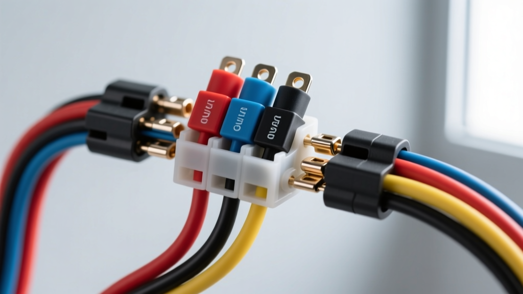
The Hidden Dangers of Quick Splice Wire Connectors in Automotive Circuits
Quick splice wire connectors—commonly referred to as T-taps, Scotchloks, or vampire taps—are notorious in the automotive electrical community. While they offer a seemingly tool-free method to tap into an existing circuit for aftermarket accessories like dash cams, LED lighting kits, or remote start modules, their insulation-displacement contact (IDC) mechanism frequently leads to high-resistance joints, galvanic corrosion, and severed wire strands. When diagnosing electrical gremlins, the quick splice is almost always the primary suspect.
Modern vehicles utilize thin-wall cross-linked polyethylene (XLPE) insulated wires such as TXL, GXL, and SXL, which are governed by the SAE J1128 Low Tension Primary Cable Standard. The tough XLPE insulation actively resists the dulling U-blade of cheap quick splices. This often results in the blade pushing the wire out of the channel rather than piercing it, or worse, shearing the fine copper strands entirely. Furthermore, the dissimilar metals used in the tap's U-blade (often brass or steel) and the vehicle's pure copper wiring create a galvanic cell when exposed to humidity, accelerating oxidation and increasing resistance over time.
Diagnostic Decision Tree: Troubleshooting Quick Splice Failures
Before grabbing a multimeter, use this symptom-based decision tree to isolate the exact failure mode of the quick splice wire connector.
Symptom 1: Intermittent Accessory Power Loss
- Trigger: Accessory works intermittently, especially when driving over bumps or when the vehicle's HVAC blower motor vibrates the chassis.
- Probable Cause: The U-blade has not fully seated into the hinge, or the copper strands were partially severed and have fatigued from vibration.
- Immediate Action: Perform the 'Tug and Wiggle' test on the branch wire while monitoring voltage at the accessory plug.
Symptom 2: Complete Circuit Failure or Blown Fuses
- Trigger: The aftermarket accessory is completely dead, or the vehicle's main circuit fuse (e.g., Cigar Lighter, Smart Junction Box) has blown.
- Probable Cause: The U-blade missed the copper conductor entirely and is resting on insulation (dead circuit), OR the tap's metal housing is exposed and shorting to ground against a metal chassis bracket.
- Immediate Action: Visually inspect the tap's seating depth and check for chassis proximity. Perform a continuity test to ground.
Symptom 3: Voltage Drop and Dim Lighting
- Trigger: Tapped accessories (like LED rock lights or interior footwell lighting) appear dim or operate below optimal capacity.
- Probable Cause: Severe galvanic corrosion at the IDC point has created a high-resistance bottleneck, choking current flow under load.
- Immediate Action: Conduct a loaded voltage drop test across the quick splice junction.
Step-by-Step Troubleshooting Flow
Follow this systematic diagnostic flow to confirm a quick splice failure and gather the data needed for a permanent repair. As outlined in AutoShop 101 Automotive Electrical Fundamentals, diagnosing high-resistance faults requires testing the circuit under a loaded state, not just checking for open-circuit voltage.
Step 1: Visual and Physical Inspection
- Locate the Tap: Trace the accessory's branch wire back to the main vehicle harness. Identify the quick splice wire connector.
- Check the Hinge: Look at the plastic housing. Is the locking tab fully engaged? A partially closed housing means the U-blade has not pierced the main wire's insulation.
- Inspect the Branch Wire: Look at where the branch wire enters the metal crimp barrel. Is the insulation crimped, or just the bare wire? A loose branch wire is a common failure point.
Step 2: Loaded Voltage Drop Testing
- Setup Multimeter: Set your digital multimeter (DMM) to DC Volts.
- Probe Placement: Place the red probe on the main vehicle wire, upstream (towards the battery) of the quick splice. Place the black probe on the branch wire, just past the metal crimp barrel.
- Apply Load: Turn on the accessory. If testing a lighting circuit, ensure the lights are on. If testing a module, wake it up via CAN-bus or ignition.
- Read the Drop: A healthy connection will show a voltage drop of less than 0.1V. If your DMM reads 1.5V, 3.0V, or higher, the quick splice is internally corroded or the U-blade has severed the main wire strands, creating a massive bottleneck.
Step 3: The CAN-Bus Integrity Check
If the quick splice was used on a CAN-bus network (e.g., tapping into GM GMLAN or Ford MS-CAN wires to trigger a remote start), the U-blade alters the twisted-pair geometry and introduces untwisted wire length. This causes signal reflection and CAN-bus termination errors. Use an oscilloscope to check the CAN-H and CAN-L waveforms. If the voltage peaks are clipped or noisy at the tap site, the quick splice has compromised the differential pair.
Quick Splice Color Codes and AWG Mating Specifications
Using the wrong size quick splice is a guaranteed path to failure. The U-blade must be sized precisely to the wire gauge to displace the insulation without cutting the copper strands. Below is the standard color coding and mating specification chart for 14-16 AWG and adjacent sizes.
| Connector Color | Target AWG Range | Common Automotive Applications | Failure Risk if Mismatched |
|---|---|---|---|
| Red | 18-22 AWG | CAN-bus lines, sensor grounds, ECU trigger wires | Using a Blue tap on 18 AWG will completely sever the fine-strand conductor. |
| Blue | 14-16 AWG | Interior lighting, radio harnesses, 12V accessory sockets | Using a Yellow tap on 16 AWG will result in zero contact; the blade won't reach the copper. |
| Yellow | 10-12 AWG | Power windows, HVAC blower motors, headlamp feeds | Using a Blue tap on 10 AWG will crush the wire and cause severe voltage drop under high amperage. |
The Proper Repair: Eliminating Quick Splices
Once a quick splice wire connector is identified as faulty, it must be removed entirely. There is no reliable way to 're-crimp' or repair the main wire once the U-blade has compromised the structural integrity of the copper strands and the XLPE insulation.
- Excise the Tap: Cut the quick splice out of the harness. You will likely need to cut back 1 to 2 inches on the main wire to remove the damaged section where the strands were crushed.
- Strip and Clean: Strip 3/8 inch of insulation from the main wire ends and the branch wire. Clean the exposed copper with electrical contact cleaner to remove any green copper oxide (verdigris) caused by galvanic corrosion.
- Parallel Crimp or Solder: For a robust repair, use a parallel crimp connector, or twist the branch wire into the main wire and solder the joint. According to TE Connectivity Automotive Crimp Guidelines, a proper mechanical crimp yields a gas-tight connection that prevents oxygen from reaching the copper.
- Seal with Adhesive Heat Shrink: Slide a piece of dual-wall, adhesive-lined heat shrink (such as 3M EPS-400) over the repair. Apply heat until the inner polyamide adhesive melts and oozes out the ends. This creates a waterproof, vibration-resistant seal that mimics factory harness standards and completely prevents future moisture intrusion.
By replacing failing quick splice wire connectors with solder-sealed or adhesive-lined crimp joints, you restore the circuit's amperage capacity, eliminate high-resistance voltage drops, and ensure the long-term reliability of the vehicle's electrical system.