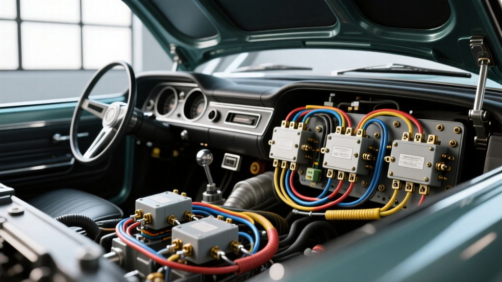
The Restomod Challenge: High-Amp AC and Cooling Upgrades
When swapping a classic muscle car or vintage truck from a factory generator to a modern high-output alternator, the electrical demands change drastically. Adding a modern aftermarket climate control system, such as a Vintage Air Gen IV unit paired with a Sanden SD7B10 compressor, alongside dual 11-inch electric cooling fans, can easily push continuous electrical loads past 60 amps. Original 14-gauge cloth-covered wiring and 4-pin glass tube fuse blocks were never designed for this amperage. Executing a comprehensive one stop auto air conditioning & electrical repair overhaul means abandoning patch-fixes and completely re-engineering the vehicle's power distribution network to handle modern accessory loads safely and efficiently.
Why a Holistic Repair and Upgrade Approach Matters
Treating an alternator swap or an AC compressor install as isolated events is a leading cause of restomod electrical fires and parasitic battery drains. A true one stop auto air conditioning & electrical repair strategy addresses the entire circuit path: from the alternator output stud to the main battery positive, through the primary fuse block, down to the relay control modules, and finally to the accessory terminals. Upgrading the alternator to a 100-amp 1-wire unit without simultaneously upgrading the main charge wire to 8 AWG cross-linked polyethylene (XLPE) wire creates a massive bottleneck. The undersized wire will act as a resistor, generating excessive heat, dropping voltage at the fuse block, and ultimately causing the AC compressor clutch to cycle erratically due to low-voltage conditions at the relay trigger pins.
Main Power Distribution and Alternator Upgrades
The foundation of any high-amperage restomod build is the main charge circuit. For a 100A to 140A alternator, you must use a minimum of 8 AWG stranded copper wire rated to SAE J1128 specifications for high-temperature engine bay environments. Standard PVC wire becomes brittle and cracks when exposed to exhaust manifold radiant heat. XLPE (Cross-Linked Polyethylene) insulation withstands temperatures up to 125 degrees Celsius, making it mandatory for routing near headers.
Ring Terminal and Fusible Link Selection
At the alternator output stud, terminate the 8 AWG wire using a heavy-duty, heat-shrink-sealed ring terminal with a 5/16-inch inner diameter. Crimp this using a hex-indent die, not a simple dot-indent crimper, to ensure a gas-tight connection that resists vibration. Between the alternator and the main distribution block, integrate a 125-amp Mega Fuse or ANL fuse within 18 inches of the battery positive terminal to protect the main harness in the event of a dead short.
Sizing Wires for Sanden AC Compressors and Electric Fans
Proper wire gauge selection prevents voltage drop, which is critical for the longevity of AC compressor clutch coils. A Sanden SD7B10 clutch typically draws 3.5 to 4.0 amps in a steady state, but the initial inrush current can spike significantly higher. If the wiring is too thin, the voltage at the clutch coil drops below 11.5 volts, causing the coil to overheat and fail prematurely.
| Circuit Component | Wire Gauge (AWG) | Max Continuous Amps | Recommended Fuse | Connector Type |
|---|---|---|---|---|
| Main Alternator Charge | 8 AWG XLPE | 100A - 140A | 125A Mega Fuse | 5/16' Ring Terminal |
| Electric Fan Primary Power | 10 AWG XLPE | 25A - 30A | 30A ATO Blade | Weather-Pack 1-Way |
| AC Compressor Clutch Power | 12 AWG XLPE | 10A - 15A | 15A ATO Blade | Weather-Pack 1-Way |
| Relay Trigger / Switch | 16 AWG TXL | 3A - 5A | 5A ATO Blade | Metri-Pack 150 |
| Binary / Trinary Safety Switch | 18 AWG TXL | 1A - 2A | Inline 3A | Deutsch DT 2-Pin |
Relay Wiring: Pinouts and Connector Selection
Never route high-amperage accessory power directly through the dashboard HVAC switches or ignition switches. Doing so will melt the switch contacts and burn the factory harness. Instead, use Bosch-style ISO mini relays to isolate the high-current load from the low-current trigger circuit.
Standard Bosch 4-Pin Relay Pin Configuration
- Pin 30 (Common Input): Connects to the fused 12V+ battery source. Use 10 AWG or 12 AWG wire depending on the load.
- Pin 87 (Normally Open Output): Connects to the positive terminal of the AC compressor clutch or electric fan motor.
- Pin 85 (Coil Ground): Connects to a clean, bare-metal chassis ground. Use a star washer to bite through paint and ensure continuity.
- Pin 86 (Coil Trigger): Connects to the 12V+ switched source from your dashboard AC toggle switch or the binary safety pressure switch.
By utilizing this relay topology, the dashboard switch only carries the negligible current required to energize the relay coil (typically less than 0.2 amps), while the heavy current flows directly from the battery to the compressor via the relay's internal contacts.
Delphi Weather-Pack Crimping and Heat Shrink Sealing
For under-hood connections, standard vinyl butt connectors are unacceptable. They allow moisture ingress, leading to galvanic corrosion and green crust on the copper strands. The industry standard for restomod engine bay wiring is the Delphi Weather-Pack connector system. These connectors feature silicone tower seals that compress around the wire insulation, creating a watertight barrier.
Step-by-Step Weather-Pack Crimping Procedure
- Strip the Wire: Strip exactly 5/16-inch of insulation from the wire end. Stripping too much leaves bare copper exposed to corrosion; stripping too little forces the insulation crimp over the bare wire, causing a high-resistance joint.
- Core Crimp: Place the terminal in the appropriate die of a Delphi 12094264 or equivalent ratcheting crimper. The smaller, forward crimp wings must bite tightly into the bare copper strands.
- Insulation Crimp: The larger, rear wings must fold over the wire's insulation jacket, providing strain relief so the core crimp is not subjected to vibration fatigue.
- Install the Seal: Slide the silicone tower seal over the wire before crimping. Once crimped, push the seal down until it bottoms out against the terminal shoulder.
- Insert into Cavity: Push the terminal into the nylon housing until you hear and feel a distinct click. Tug gently on the wire to verify the terminal lock tang has engaged the housing barb.
- Use Cavity Plugs: If a connector housing has unused cavities, you must insert rubber cavity plugs. Leaving them empty defeats the waterproof nature of the connector and allows water to track across adjacent pins.
Testing and Troubleshooting Voltage Drop
After assembling your one stop auto air conditioning & electrical repair harness, you must verify circuit integrity using a voltage drop test. A multimeter set to DC Volts is the only way to identify hidden resistance that a simple continuity test will miss.
Executing the Voltage Drop Test
With the engine running and the AC compressor clutch engaged, place the red probe of your multimeter on the alternator output stud and the black probe on the battery positive post. A reading higher than 0.2 volts indicates excessive resistance in the main charge wire, requiring you to inspect your ring terminal crimps or upgrade to a thicker gauge wire. Next, test the clutch circuit by placing the red probe on the relay Pin 30 input and the black probe on the compressor clutch positive terminal. Again, any reading above 0.2 volts under load indicates poor connections, undersized wiring, or corroded Weather-Pack pins. By adhering to these rigorous Vintage Air installation standards and SAE wiring protocols, your restomod will deliver ice-cold air and reliable electrical performance for thousands of miles.