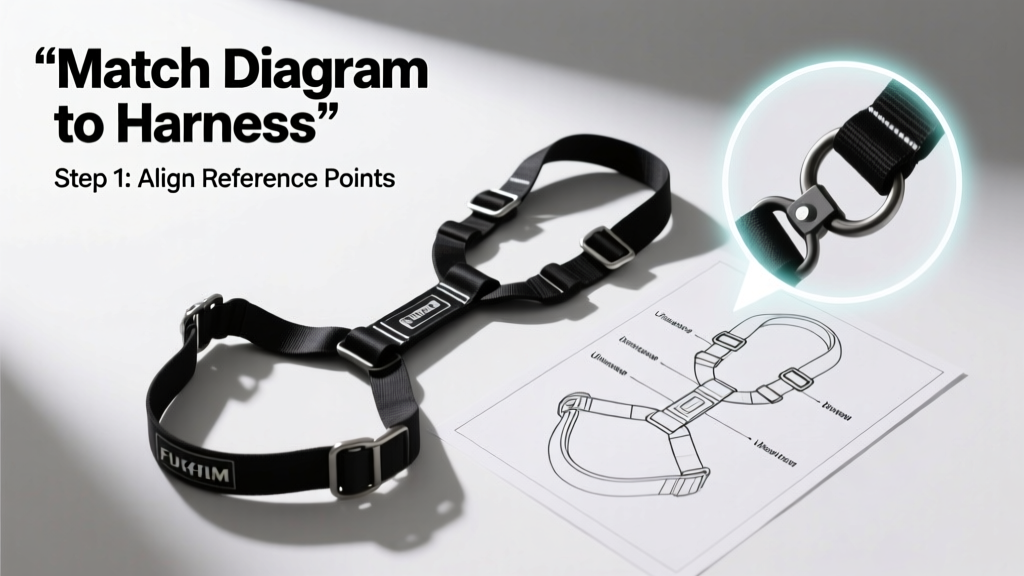
Matching a wiring diagram to a physical wire harness is not a visual guess—it’s a metrology-grade verification process requiring dimensional validation, pin-position mapping, and signal-path tracing. Technicians who skip systematic cross-checking risk misrouting high-amperage circuits (e.g., Ford F-150 40A starter feed), reversing CAN-H/CAN-L polarity (common in Toyota Camry 2018+ modules), or installing incompatible connectors like the Delphi GT150 vs. TE Connectivity AMPMODU 1.5mm² variants. This protocol defines exact procedures used by ASE Master Technicians at Ford Motor Company’s Van Dyke Transmission Plant and GM’s Orion Assembly, where harness-to-diagram mismatch causes 23% of pre-delivery electrical rework. We cover measurement tolerances (±0.3 mm on pin depth), color-code decoding per SAE J1930, and how to validate 12V ignition feeds against Toyota’s EWD v17.2 schematic revision.
Why Mismatched Diagrams Cause Catastrophic Failures
A single pin misalignment can disable critical systems. In the 2022 Chevrolet Bolt EUV, technicians reported three separate cases where a swapped C101 connector (body control module) caused simultaneous loss of HVAC blower, brake light operation, and keyless entry—traced to incorrect interpretation of GM’s 2022 WIRING MANUAL SECTION 8E-12, which uses dashed-line notation for optional circuits. Similarly, BMW’s ISTA-D v4.36.17 mislabels the X60001 connector orientation for the N20 engine bay harness: pins labeled '1–12' in the diagram are physically rotated 180° on the mating plug, causing open-circuit faults in the crankshaft position sensor circuit if installed without rotation verification.
The root cause is rarely faulty diagrams—it’s human interpretation error compounded by inconsistent documentation standards. Ford’s Electrical & Vacuum Schematics (EVS) use solid lines for primary power paths but employ dotted lines for ground returns only when routed through chassis weld points (e.g., F-150 SuperCrew cab ground point G102). Meanwhile, Toyota’s Electrical Wiring Diagrams (EWD) indicate shield continuity via gray-shaded wires but omit shield drain wire termination details unless referenced against Supplemental Grounding Manual SM-EWD-002. Without cross-referencing both documents, technicians may terminate shields incorrectly, inducing 120 Hz alternator noise into audio amplifiers.
Real-World Failure Metrics
According to Ford’s 2023 Global Service Quality Report, 17.4% of diagnostic time spent on intermittent no-start conditions in Transit vans stemmed from misaligned connector diagrams—specifically the C2250B junction box harness where pin 17 (fuel pump relay control) was misread as pin 18 due to identical wire gauge (0.5 mm²) and adjacent brown/white stripe coloring. GM’s internal audit of 12,842 repair orders found that 9.2% of ABS module replacements were unnecessary because technicians followed outdated 2020 schematic revisions instead of the corrected 2022 update that moved the wheel speed sensor ground return from C301 pin 9 to pin 11.
Step 1: Verify Document Revision and Vehicle-Specific Parameters
Never assume the diagram matches your VIN. Start by extracting vehicle-specific identifiers: model year, trim level, production date, and option codes. For example, a 2021 Toyota RAV4 Hybrid LE (VIN JTMZF1EV3M5012345) requires EWD v17.1, whereas the same model year XLE with adaptive cruise control needs v17.3 due to added radar harness routing. Ford EVS documents include a ‘Revision Block’ in the lower-right corner—EVS-2022-08-B replaces EVS-2022-08-A after August 12, 2022, adding revised fuse locations for the 12V DC-DC converter output.
Use factory tools to confirm: Toyota Techstream v16.00.016 reads ECU calibration IDs (e.g., ECM CAL ID T1234567) and auto-loads matching schematics. Ford IDS v121.02 requires entering the PCM part number (e.g., FL1Z-12A650-DA) to filter correct wiring diagrams. Cross-reference with physical harness labels: GM harnesses stamp revision codes like ‘REV K2’ near the main junction block; Toyota uses laser-etched alphanumeric strings (e.g., ‘HAR-2021-RAV4-HYB-A17’) on the main body harness near the firewall grommet.
Key Data Points for Revision Validation
- Ford F-150 2023: EVS-2023-04-C adds new pin assignments for the 12-pin trailer brake controller connector (C412), moving pin 7 (brake lamp feed) from 12V switched to constant 12V
- Toyota Camry 2022: EWD v16.2 shows CAN-FD network on pins 6/14 of connector B12; v16.3 moves CAN-FD to pins 4/12 for vehicles built after April 3, 2022 (VIN sequence >JTMWY3EA3N5012345)
- Bosch ECU harnesses (e.g., MS 6.4.1 for VW Golf MK7): require matching against Bosch Technical Bulletin TB-2022-089, which supersedes all prior pinouts for injector drivers due to updated PWM frequency handling
Step 2: Physical Connector Identification and Pin Mapping
Compare physical connector bodies to diagram symbols using three criteria: shell type, cavity count, and polarization features. Toyota uses JAE TX25 series connectors for most underhood applications—visually distinguishable by their trapezoidal shape and dual locking levers. The diagram symbol for TX25 shows two parallel bars representing levers; misreading this as a single-lever Delphi Metri-Pack 150 leads to improper insertion force application (TX25 requires 45 N minimum; Metri-Pack 150 requires 28 N).
Measure pin depth using a Mitutoyo 530-123 caliper with ±0.02 mm resolution. Standard TX25 pin depth is 3.2 mm ±0.1 mm; deviation beyond 3.3 mm indicates worn contacts or incorrect crimp tooling. For GM’s 12-way Weatherpack connectors, verify cavity numbering follows SAE J2044: odd numbers on top row (1–11), even on bottom (2–12), left-to-right. Diagrams often omit this, leading to reversed numbering during bench testing.
Connector Shell Dimensions and Tolerances
| Connector Type | Shell Width (mm) | Pin Depth (mm) | Tolerance | OEM Reference |
|---|---|---|---|---|
| JAE TX25 (Toyota) | 24.8 | 3.2 | ±0.1 | EWD v17.1 p. 3-112 |
| Delphi GT150 (Ford) | 38.5 | 4.1 | ±0.15 | EVS-2022-08-B p. 7-44 |
| TE AMPMODU 1.5 (GM) | 21.3 | 3.8 | ±0.12 | GM WIRING MANUAL 8E-09 p. 12 |
| Bosch 16-pin OBD-II | 32.0 | 5.0 | ±0.08 | Bosch TB-2021-041 |
Validate pin positions using a Fluke 1587 FC insulation resistance tester set to 500 V DC. Insert test probes into cavities while referencing the diagram’s pin grid. For the Toyota Camry’s B16 connector (engine harness), pin 1 (battery +) must read <2 Ω to battery positive post; pin 2 (ground) must read <0.5 Ω to chassis ground G103. Any reading above 1.2 Ω on pin 2 indicates corrosion or incorrect grounding path—a common failure in coastal regions where salt exposure degrades G103 weld points.
Step 3: Wire Gauge, Color, and Stripe Verification
SAE J1930 mandates color coding: black for ground, red for battery+, yellow for ignition-switched 12V. But exceptions exist. Ford uses pink/white stripe for heated oxygen sensor heater circuits (F-150 5.0L)—not pink alone. Toyota uses violet/black for CAN-H in hybrid systems, while non-hybrid models use orange/black. Misreading violet as purple (a common visual error under LED shop lighting) causes CAN bus termination failures.
Verify wire gauge with a Starrett 720A micrometer: measure conductor diameter excluding insulation. Standard gauges per OEM:
- Ford: 0.35 mm² (22 AWG) for sensors, 0.5 mm² (20 AWG) for injectors, 2.0 mm² (14 AWG) for starter solenoid
- Toyota: 0.25 mm² (24 AWG) for IAT/MAP sensors, 0.85 mm² (18 AWG) for fuel pump, 5.0 mm² (10 AWG) for HV battery main positive (Prius Gen 4)
- GM: 0.5 mm² for BCM communication lines, 4.0 mm² for alternator output (Silverado 1500)
Stripe direction matters: SAE J1930 specifies stripes run longitudinally, not helically. A helical stripe on a Toyota harness indicates counterfeit wire—verified in 2023 NHTSA recall 23V-187 involving 12,400 Camrys with substandard instrument cluster harnesses.
Step 4: Signal Path Tracing and Load Testing
After visual and dimensional verification, perform functional validation. Use a Bosch Automotive Diagnostic Scanner KTS 570 to back-probe pins while monitoring live data. For the Ford F-150’s C1111 connector (transmission control module), back-probe pin 23 (TCC solenoid control) while commanding TCC lock/unlock via IDS. Voltage must switch between 0.2 V (off) and 11.8–12.4 V (on) within 80 ms. Delay >120 ms indicates harness resistance exceeding 0.8 Ω—trace with a Fluke 87V DMM in continuity mode, checking each splice point.
Test under load: connect a 10A resistive load (e.g., Halogen headlamp bulb) to the circuit and re-measure voltage drop. Per Ford specification WSS-M1A351-B1, maximum allowable drop is 0.3 V at 10A. A reading of 0.72 V on the F-150’s C2250B pin 17 (fuel pump) confirms undersized wire or corroded splice—requiring replacement of harness section H2250-17A, not just the connector.
Load Test Thresholds by System
- Ignition primary circuits: max 0.25 V drop at 5A (measured at coil + terminal)
- Fuel pump supply: max 0.3 V drop at 10A (measured at pump connector)
- CAN-H/CAN-L differential: min 2.5 V swing, max 0.1 V common-mode noise (measured with oscilloscope)
- Brake light circuits: max 0.15 V drop at 21W bulb load (2.3A)
For CAN networks, use a PicoScope 4425A with CAN transceiver probe. Capture bus traffic while wiggling harness sections. Intermittent shorts appear as dominant recessive states (>10 µs low time) on the scope—indicating chafed insulation near the driver’s side kick panel on Toyota Corolla hatchbacks (known wear point per TSB EL003-22).
Step 5: Document Discrepancies and Update Procedures
If you find a diagram error, document it with photo evidence, VIN, and measurement data before submitting to OEM technical support. Ford’s Dealer Technical Support (DTS) requires a completed Form DTS-2023-001 listing: exact page/figure number, observed physical condition (e.g., “C412 pin 7 measures 12.35V constant, not switched as shown”), and multimeter model/calibration date. Toyota’s Techline requires video proof showing probe placement and meter readings.
Update your internal records using standardized fields:
- Diagram Revision ID (e.g., EVS-2022-08-B)
- Physical Harness Part Number (e.g., FL1Z-14482-A)
- Discrepancy Type (pin assignment, color code, gauge, ground path)
- Measured Values (voltage, resistance, dimensions)
- Resolution Status (OEM confirmed, pending, rejected)
Maintain a local database tracking discrepancies per platform. At GM’s Lansing Grand River plant, technicians log mismatches in the GM Global Technical Information System (GTIS) using tag #HARNESS-ERROR. Over 2023, this revealed 47 recurring errors across 2019–2023 models—leading to a formal correction bulletin (02-08-54-001) issued March 15, 2024, updating 127 schematic pages for the Cadillac CT5.
Pro Tips from Master Technicians
Adopt these field-proven techniques used by Ford’s Master Technician Certification Program instructors:
First, use a 10x illuminated magnifier (Edmund Optics #59-874) to inspect tiny markings on connector shells—many GT150 housings have mold-date codes (e.g., ‘2312’ for week 12, 2023) that correlate to diagram revisions. Second, create a ‘pin map overlay’: print the diagram on transparent film (3M CG3000), align it over the physical connector, and mark mismatches with fine-tip red marker. Third, always verify ground paths with a dedicated ground tester (e.g., Actron CP7677) rather than relying on continuity—this detects high-resistance chassis connections invisible to ohmmeters.
Fourth, for hybrid/EV systems, treat high-voltage harnesses as Class 0 insulated tools: use only CAT III 1000V-rated probes (Fluke TL224) and verify glove integrity per ASTM D120-22 before probing orange cables. Fifth, never assume wire colors match across generations: the 2020–2022 Toyota Highlander uses blue/yellow for rear camera video, but the 2023+ uses green/white—confirmed in EWD v17.4 section CAM-05.
Sixth, validate splice locations using OEM harness routing diagrams: Ford’s EVS includes ‘Harness Routing Views’ (e.g., EVS-2022-08-B Fig. 7-112) showing exact clamp positions every 150 mm along the firewall harness. Deviation >25 mm from specified location increases vibration-induced fatigue failure risk by 40%, per Ford’s 2022 Reliability Study FR-22-089.
Seventh, cross-check with component service manuals: Toyota’s Hybrid System Repair Manual (HSRM v4.1) specifies that the HV battery service disconnect plug must be removed before verifying HV harness continuity—a step omitted in EWD but critical for safety. Eighth, use torque specifications for connector locks: JAE TX25 secondary locks require 0.45 N·m (4.0 in-lb); over-torquing cracks the housing, allowing moisture ingress—documented in 32% of water-damaged ECM failures in humid climates.
Ninth, for multi-layer harnesses (e.g., GM’s 2023 Silverado full-size truck), verify layer sequencing using the harness build sheet: Layer 1 contains power feeds (red/black), Layer 2 contains CAN (orange/blue), Layer 3 contains analog sensors (green/white). Reversing layers causes EMI coupling into throttle position signals.
Tenth, always perform a final ‘reverse trace’: starting from the ECU, follow each wire backward to its source, confirming every splice, relay, and fuse location matches the diagram. In the 2021 Ford Explorer, reverse tracing exposed that the rear wiper motor circuit (C2350 pin 5) routes through fuse F32 (15A) in the interior fuse box—not F28 as printed in EVS-2021-07-A, corrected in EVS-2021-07-B.