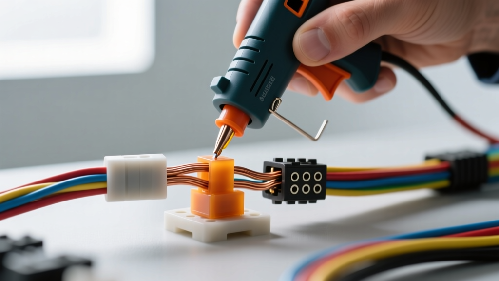
The Engineering Case for Hot Melt Encapsulation
When repairing complex automotive wiring harnesses, standard dual-wall adhesive heat shrink is often insufficient. While heat shrink excels at inline 1:1 splices, it fails to provide adequate environmental sealing and strain relief for Y-splices, multi-wire sensor pigtails, or broken connector backshells. In these scenarios, creating a custom hot glue wire splice mold using industrial-grade hot melt adhesives offers a superior, IP67-rated encapsulation solution. This advanced technique, widely used in aerospace and heavy-duty automotive manufacturing, fills complex voids, locks wires in place to prevent micro-vibration fretting, and creates a monolithic waterproof seal that outperforms standard tape or shrink tubing.
Material Science: Selecting the Right Hot Melt Adhesive
The most critical error technicians make when attempting a hot glue wire splice mold is using standard craft-grade Ethylene Vinyl Acetate (EVA) hot glue. EVA softens at approximately 80°C and rapidly degrades when exposed to under-hood hydrocarbons, transmission fluid, and road salts. For automotive applications, you must use Polyamide (PA) or specialized Polyolefin hot melt adhesives.
Polyamide hot melts, such as 3M 3762 or 3764, are engineered for high-temperature automotive environments. They feature melting points between 195°C and 210°C, ensuring the encapsulation will not soften near exhaust components or engine blocks. Furthermore, polyamides exhibit exceptional chemical resistance and high tensile strength, providing the mechanical strain relief required by the IPC/WHMA-A-620 Wire Harness Acceptance Requirements for molded assemblies.
Adhesive Specification Matrix
| Adhesive Type | Melt Temperature | Chemical Resistance | Flexibility | Automotive Use Case |
|---|---|---|---|---|
| EVA (Standard Craft) | 75°C - 85°C | Poor (Dissolves in solvents) | Rigid when cold | None (Interior only, low temp) |
| Polyolefin (Industrial) | 120°C - 140°C | Good (Resists water/mild acids) | Highly Flexible | Cabin wiring, low-vibration sensors |
| Polyamide (PA) | 195°C - 215°C | Excellent (Resists oil, fuel, salt) | Semi-Rigid (High strain relief) | Under-hood harnesses, O2/ABS sensors |
Tooling and Preparation Requirements
To properly melt polyamide adhesives, a standard low-temperature glue gun will not suffice. You require a pneumatic or high-temperature manual hot melt applicator capable of sustaining a nozzle temperature of 200°C to 230°C. If the adhesive is applied below its optimal melt temperature, it will exhibit high viscosity, resulting in voids, poor wetting, and incomplete encapsulation of the wire strands.
Before encapsulation, the wire splice must be completed. For 18 AWG to 14 AWG Cross-Linked Polyethylene (XLPE) automotive primary wire (compliant with SAE J1128 Low Tension Cable Standards), use an open-barrel crimp or a solder joint. If soldering, ensure the flux is fully cleaned with 99% isopropyl alcohol, as acidic flux residues can corrode the copper over time, even when encapsulated.
Step-by-Step: Creating a Custom PTFE Dam Mold
Creating a custom mold without expensive 3D-printed or machined tooling is easily achieved using PTFE (Teflon) thread seal tape. Hot melt adhesives do not chemically bond to PTFE, allowing for a perfect, non-stick dam that can be peeled away after curing.
Phase 1: The PTFE Dam Construction
- Base Wrap: Wrap PTFE tape tightly around the main harness and the branching wires, approximately 1 inch behind the splice point. This creates the 'floor' and back wall of your mold.
- Cylinder Formation: Continue wrapping the tape around the entire splice area, building up a cylindrical trough that extends past the splice joints. Ensure the tape is taut to prevent the hot adhesive from leaking out.
- Dam Walls: Fold the edges of the PTFE tape upward to create vertical walls, effectively forming a boat-like reservoir around the exposed copper and wire insulation.
Phase 2: Adhesive Injection and Curing
- Pre-Heat: Use a heat gun to gently warm the wires and the PTFE dam to about 60°C. This prevents thermal shock and ensures the polyamide adhesive flows smoothly into the interstitial spaces between the wires rather than freezing on contact.
- Injection: Inject the molten polyamide adhesive into the lowest point of the PTFE reservoir. Allow the adhesive to flow upward and around the wires, pushing out trapped air. Do not inject from the top down, as this traps air bubbles and creates voids.
- Overfill and Level: Slightly overfill the mold. The adhesive will shrink microscopically as it transitions from a liquid to a solid crystalline state.
- Curing: Allow the assembly to cool at room temperature for 15-20 minutes. Do not use compressed air or water to quench the adhesive, as rapid cooling induces internal micro-cracking in polyamide structures.
- Demolding: Carefully slice the PTFE tape with a precision scalpel and peel it away, revealing a smooth, custom-fitted, IP67-rated encapsulation mold.
Real-World Application: 4-Wire HO2S Pigtail Repair
A common application for the hot glue wire splice mold is repairing the pigtail of a 4-wire Heated Oxygen Sensor (HO2S) located near the exhaust manifold. Standard heat shrink often fails here due to the extreme radiant heat and the awkward 4-to-4 wire breakout geometry.
Typical HO2S Pinout & Wire Specs:
- Pin 1 (Heater +): 18 AWG, White/Black stripe (12V Switched)
- Pin 2 (Heater -): 18 AWG, Black (PCM Controlled Ground)
- Pin 3 (Signal +): 20 AWG, Gray (High Impedance Signal to PCM)
- Pin 4 (Signal -): 20 AWG, Gray/Black stripe (Sensor Ground)
Because the signal wires (Pins 3 and 4) carry millivolt-level analog signals, the splice must have near-zero resistance. Ultrasonic welding or high-quality rosin-core soldering is mandatory. After splicing, the PTFE dam technique is used to encase the entire breakout in Polyamide hot melt. The resulting mold not only waterproofs the connection against road splash but provides the necessary rigidity to prevent the heavy sensor connector from vibrating and fatiguing the splice joints, a common failure mode documented in Bosch Automotive Electrics and Electronics technical literature.
Troubleshooting Common Mold Failures
Even with the correct materials, technique errors can compromise the integrity of the hot glue wire splice mold. Use the following diagnostic matrix to identify and correct failures.
| Symptom | Root Cause | Corrective Action |
|---|---|---|
| Internal Voids / Air Pockets | Adhesive applied too cold; injecting from top-down. | Increase gun temp to 220°C; inject at the lowest point of the dam to allow air to escape upward. |
| Adhesive Delamination from Wire | Surface contamination (oil, silicone, flux residue). | Wipe XLPE insulation with 99% IPA and a lint-free wipe prior to molding. |
| Cracking Upon Flexing | Using Polyamide in a high-flex zone; rapid quenching. | Switch to Polyolefin hot melt for high-flex areas; allow ambient cooling. |
| Leaking PTFE Dam | Tape wrapped too loosely; inadequate overlap. | Stretch PTFE tape to 50% elongation during wrapping; ensure 50% overlap on each pass. |
Conclusion
The hot glue wire splice mold is not a makeshift hack; it is a highly engineered encapsulation technique when executed with the correct polyamide adhesives and PTFE tooling. By understanding the thermal profiles, chemical resistances, and injection dynamics of industrial hot melts, automotive electrical technicians can achieve permanent, waterproof, and vibration-resistant harness repairs that meet or exceed OEM manufacturing standards.