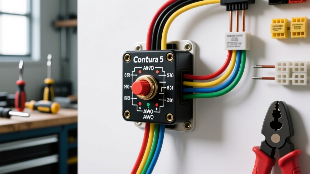
Introduction to Contura V-Series Rocker Switches
When designing a custom auxiliary switch panel for off-road vehicles, marine applications, or heavy-duty trucks, the Carling Contura V-series (and its widespread aftermarket clones) remains the industry standard. Understanding the exact rocker switch wire diagram is critical to preventing melted harnesses, parasitic battery drain, and backlight failures. Unlike simple single-pole single-throw (SPST) toggles, modern illuminated rocker switches utilize multi-pole configurations to independently manage high-amperage load circuits and low-amperage LED illumination circuits.
This technical reference provides exact pinout specifications, wire gauge matrices, and relay integration protocols for 5-pin and 7-pin Contura-style rocker switches. All wiring recommendations adhere to SAE J1128 Low Tension Primary Cable standards and standard ISO mini-relay configurations.
5-Pin Rocker Switch Anatomy and Pinout
The standard 5-pin illuminated rocker switch is technically a Dual-Circuit SPST (Single Pole, Single Throw) device. It controls one primary load circuit while simultaneously managing a single internal LED illuminator. The physical terminals on the rear housing are typically numbered 2, 3, 6, 7, and 8.
Terminal Specification Matrix (5-Pin)
| Terminal Pin | Function | Standard Wire Color | AWG Size | Connection Destination |
|---|---|---|---|---|
| 2 | Line 1 Input (Load Power) | Red | 18 AWG | Fused 12V+ Source (Ignition or Battery) |
| 3 | Line 1 Output (Switched Load) | Blue | 18 AWG | Relay Pin 86 (Coil Power) |
| 6 | Lamp Ground (Lower LED) | Black | 20 AWG | Chassis Ground or Ground Busbar |
| 7 | Lamp Power (Upper LED Input) | Red (Jumper) | 18 AWG | Jumpered to Pin 2 (for simultaneous illumination) |
| 8 | Lamp Ground (Upper LED) | Black/White | 20 AWG | Chassis Ground (or left disconnected if single LED) |
Expert Note: Many aftermarket 5-pin switches only populate terminals 2, 3, and 6. If your switch only has three physical spades, it lacks the independent upper/lower LED control. In this case, Pin 2 is 12V+ In, Pin 3 is 12V+ Out, and Pin 6 is LED Ground.
7-Pin DPST Rocker Switch Specifications
For applications requiring independent control of two separate accessories (e.g., a roof rack light bar and a winch solenoid) from a single switch body, the 7-pin DPST (Dual Pole, Single Throw) variant is required. This switch features two completely isolated internal circuits.
Terminal Specification Matrix (7-Pin)
| Terminal Pin | Circuit | Function | Wire Color Code |
|---|---|---|---|
| 1 | Line 2 | Line 2 Input (Load Power 2) | Red/White Tracer |
| 4 | Line 2 | Line 2 Output (Switched Load 2) | Blue/White Tracer |
| 2 | Line 1 | Line 1 Input (Load Power 1) | Red |
| 3 | Line 1 | Line 1 Output (Switched Load 1) | Blue |
| 6 | Illumination | LED Ground (Shared) | Black |
| 7 | Illumination | LED 12V+ Input | Orange (Daisy-chained to dash lighting) |
| 8 | Illumination | LED Ground 2 (Independent) | Black/Yellow Tracer |
Proper Relay Integration (The Bosch ISO Standard)
A common and catastrophic mistake in custom installs is routing high-amperage accessory loads (like 100W LED pods or air compressors) directly through the rocker switch contacts. While the switch may be stamped '20A', continuous DC loads will cause internal carbon tracking, voltage drop, and eventual thermal meltdown of the 0.250-inch quick-disconnect terminals.
The switch should only be used to trigger the low-amperage coil of a standard ISO 7588 Mini Relay. According to Littelfuse Mini ISO Relay specifications, a standard relay coil draws between 120mA and 150mA. This keeps the rocker switch contacts virtually cold, ensuring a lifespan of over 100,000 mechanical cycles.
Switch-to-Relay Wiring Sequence
- Switch Pin 2: Connect to a fused 12V+ source (use a 5A inline fuse for the switch circuit).
- Switch Pin 3: Route this switched 12V+ output to Relay Pin 86 (Coil Positive).
- Relay Pin 85: Connect to a clean, bare-metal chassis ground (Coil Negative).
- Relay Pin 30: Connect directly to the vehicle battery positive via a primary fuse sized for the actual accessory load (e.g., 30A fuse for a 20A light bar).
- Relay Pin 87: Route to the positive terminal of the accessory load.
- Accessory Ground: Ground the accessory directly to the chassis or battery negative.
Wire Gauge (AWG) and Voltage Drop Calculations
Selecting the correct wire gauge is dictated by the amperage of the circuit and the total length of the wire run (positive + negative). For the rocker switch trigger legs (Pins 2, 3, 6, 7, 8), 18 AWG primary wire is the standard. However, the load side of the relay requires strict adherence to AWG charts to prevent voltage drop, which severely dims halogen/LED lighting and starves electric motors.
| Max Continuous Load | Wire Run (Under 10 ft) | Wire Run (10 - 20 ft) | Wire Run (20 - 40 ft) | Recommended Fuse |
|---|---|---|---|---|
| 10 Amps | 16 AWG | 14 AWG | 12 AWG | 15A ATO |
| 20 Amps | 14 AWG | 12 AWG | 10 AWG | 25A ATO |
| 30 Amps | 12 AWG | 10 AWG | 8 AWG | 35A ATO |
| 40 Amps | 10 AWG | 8 AWG | 6 AWG | 50A MIDI |
Terminal Crimping and Connection Standards
Contura switches utilize standard 0.250-inch (6.35mm) male spade terminals. Using improper crimping techniques is the leading cause of intermittent switch failures in high-vibration environments (e.g., Jeep Wranglers, Ford Super Duty trucks).
- Terminal Type: Use fully insulated, nylon-crimped female quick-disconnects. Avoid bare metal spades to prevent accidental shorting against the switch panel housing.
- Crimp Tool: Use a dedicated ratcheting terminal crimper (e.g., IWISS or Titan). A proper crimp should withstand a 20 lb pull-test without the wire slipping from the barrel.
- Moisture Protection: In marine or open-cab environments, apply a small dab of dielectric grease (such as CRC or Permatex) inside the female spade terminal before pushing it onto the switch pin to prevent galvanic corrosion.
Troubleshooting Illumination and Load Failures
When a custom switch panel fails, use this diagnostic matrix to isolate the fault before replacing components.
Symptom: Switch Illuminates, But Accessory Does Not Activate
- Cause 1: Relay coil ground (Pin 85) is faulty. Fix: Test continuity between Relay Pin 85 and the chassis using a multimeter. Resistance should be less than 0.5 ohms.
- Cause 2: Blown primary load fuse at Relay Pin 30. Fix: Inspect the high-amperage fuse block near the battery.
- Cause 3: Switch Pin 3 is not outputting 12V+. Fix: Internal switch contacts are burnt. Replace the switch body.
Symptom: Accessory Activates, But Switch Does Not Illuminate
- Cause 1: Missing ground at Switch Pin 6. The LED circuit requires a dedicated ground path; it does not ground through the load circuit. Fix: Verify continuity from Pin 6 to the negative battery terminal.
- Cause 2: If using a 7-pin switch with independent dash-lighting integration, Switch Pin 7 is not receiving 12V+ when the headlights are turned on. Fix: Tap into the vehicle's OEM headlight switch illumination wire (often Orange or Brown/White depending on the OEM) to feed Pin 7.
Symptom: Switch Backlight Flickers or is Dim
- Cause: Voltage drop on the LED ground wire due to undersized wire or a poor chassis ground location. Fix: Upgrade the LED ground wire to 18 AWG and terminate it at a centralized, sanded ground busbar rather than a random sheet-metal screw. For more on proper grounding techniques, refer to the Blue Sea Systems Switch Selection and Grounding Guide.
By strictly following this rocker switch wire diagram and adhering to relay-triggered architectures, your custom automotive electrical system will remain reliable, safe, and immune to the thermal failures that plague amateur installations.