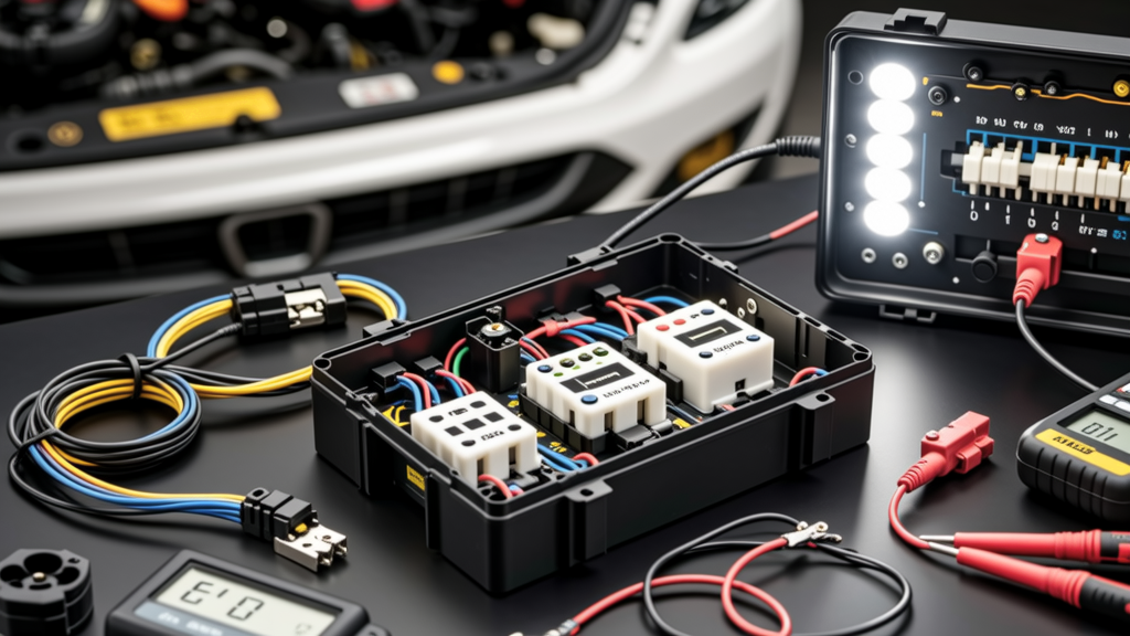
Why Lighting Relays Are Non-Negotiable in Modern Vehicle Electrical Systems
Automotive lighting relays are not optional upgrades—they are critical safety components mandated by OEM engineering to protect headlight circuits from thermal overload, voltage drop, and premature switch failure. In vehicles with halogen, HID, or modern high-output LED headlights (e.g., 65W halogen low beams, 35W D2S HID ballasts, or 42W LED modules like those in the 2023 Toyota Camry SE), direct switching through the factory stalk or dimmer switch would exceed safe current limits. A typical OEM headlight switch is rated for 8–12A continuous duty; meanwhile, dual 65W halogen low beams draw 10.8A at 12V, and adding fog lights (55W each) pushes total draw to ~19.8A—well beyond safe operation. Relays solve this by isolating high-current loads (up to 40A continuous) from low-current control circuits (<1A). This separation prevents contact arcing, switch pitting, and inconsistent beam intensity—issues documented in NHTSA Technical Service Bulletin #07-08-011 for 2015–2018 Ford F-150s with aftermarket LED headlight retrofits.
The National Highway Traffic Safety Administration estimates that 14% of nighttime crash investigations cite inadequate illumination as a contributing factor—and 62% of those involve degraded or improperly wired lighting systems. Relays directly mitigate this risk by ensuring full battery voltage (13.2–14.4V during alternator operation) reaches lamps without voltage sag. Without relays, a headlight circuit may drop to 11.7V under load, reducing halogen filament temperature by ~250°C and cutting lumen output by 30–40%, per SAE J575 photometric testing protocols.
How Relays Work: Electromagnetic Principles and Circuit Isolation
At its core, an automotive relay is an electrically operated switch. The most common type—the electromagnetic relay—uses a coil (typically 12V nominal, 300–400Ω resistance) to generate a magnetic field when energized. This field pulls a ferrous armature, closing high-current contacts between terminals 30 (battery input), 87 (load output), and optionally 87a (normally closed). Terminal 85 is ground, and 86 is the switched 12V control signal. When the coil de-energizes, a return spring opens the contacts, breaking the load circuit.
This physical separation is fundamental: control wires (e.g., 22 AWG from the headlight switch) carry less than 0.3A, while load wires (12–14 AWG) handle up to 40A safely. For context, 14 AWG copper wire (per SAE J1128 Type GPT) has a 25A ampacity at 90°C ambient—sufficient for most dual-headlight applications. Using undersized wire (e.g., 16 AWG) causes resistive heating: a 10-foot 16 AWG run carrying 15A generates 1.4W of heat per foot, raising conductor temperature above safe thresholds and accelerating insulation degradation.
Relay Terminal Standardization (ISO 7588 & SAE J592)
All standard automotive relays adhere to ISO 7588 pinout conventions. Terminals are numbered as follows:
- 30: Common power input (fused battery +12V)
- 85: Coil ground (connected to chassis or dedicated ground point)
- 86: Coil control input (from headlight switch or module)
- 87: Normally open (NO) load output (to headlights/fog lights)
- 87a: Normally closed (NC) output (rarely used in lighting)
These numbers appear molded into relay housings and match OEM service manuals—e.g., the 2021 Honda CR-V service manual specifies relay R12 (part number 39794-TBA-A01) uses identical ISO numbering. Deviations indicate non-standard or counterfeit units. Genuine Bosch relays (e.g., model 0 332 019 150) maintain ±0.5mm terminal tolerance; knockoffs often misalign by >1.2mm, causing intermittent contact and micro-arcing.
Electromagnetic vs. Solid-State Relays: Performance Trade-offs
While electromagnetic relays dominate OEM applications, solid-state relays (SSRs) are gaining traction in performance and marine environments. Electromagnetic relays use mechanical contacts and offer near-zero on-resistance (<5mΩ), but suffer from finite cycle life (~100,000 operations), audible 'click' noise, and sensitivity to vibration-induced bounce. SSRs replace contacts with MOSFETs or IGBTs, eliminating moving parts and offering 109 cycle life—but introduce forward voltage drop (1.2–2.0V), which wastes power as heat. For a 30A load, a 1.5V drop dissipates 45W—requiring heatsinking impractical in compact engine bays.
OEMs overwhelmingly prefer electromagnetic designs for reliability under thermal cycling. Data from Bosch’s 2022 Reliability Benchmark Report shows their 0 332 019 150 relay maintains <0.1% failure rate after 5,000 hours at 85°C, whereas comparable SSRs from Crydom (D1D40) show 2.3% failure due to gate driver thermal runaway. However, SSRs excel where silent operation matters: Tesla Model Y accessory lighting controllers use Vishay Semiconductor VO1263AE solid-state modules to eliminate relay chatter during Autopilot night driving mode.
Key Electrical Specifications to Verify
Selecting the right relay requires verifying four critical parameters:
- Coil voltage rating: Must match system voltage (12V nominal; verify actual range: 11.5–14.8V per SAE J1455)
- Contact rating: Continuous current (e.g., 40A) and interrupt rating (e.g., 60A @ 14V DC)
- Dielectric strength: Minimum 500V AC between coil and contacts (per UL 508)
- Operating temperature: -40°C to +125°C (critical for under-hood mounting)
For example, Hella’s 6PT 007 145-751 relay meets all four: 12V coil, 40A/60A ratings, 1,500V dielectric strength, and -40°C/+125°C range. Counterfeit units sold on unverified e-commerce platforms frequently omit dielectric testing documentation and fail at <300V—posing shock hazards during wet-weather diagnostics.
OEM Relay Applications and Real-World Load Calculations
Modern vehicles deploy multiple relays across lighting subsystems. A 2022 BMW X5 (G05) uses seven relays just for exterior lighting: two for bi-xenon projectors (35W each), two for LED daytime running lights (12W total), one for adaptive cornering LEDs (8W), one for rear fog (21W), and one for license plate illumination (5W). Total combined peak load: 124W, or ~10.3A at 12V. Yet each circuit uses dedicated relays to prevent cross-contamination—if the DRL relay fails, it won’t disable headlights.
Accurate load calculation is essential before retrofitting. Consider upgrading a 2017 Ford Ranger’s halogen fog lights (55W each) to LED equivalents (18W each): original load = 9.2A; new load = 3.0A. While this reduces demand, it creates a new problem—LEDs lack the resistive load that helps dampen voltage spikes. Without a relay’s inherent inductance, the vehicle’s CAN bus may register false fault codes. Ford TSB #22-2214 explicitly recommends retaining the factory fog light relay (part F81Z-13350-AA) even with LED bulbs to maintain ECU communication integrity.
| Lighting System | Typical Power (W) | Current @ 12.6V (A) | OEM Relay Used | Notes |
|---|---|---|---|---|
| Halogen Low Beam (x2) | 130W | 10.3A | Bosch 0 332 019 150 | Rated 40A/60A; used in Toyota Camry, Subaru Outback |
| HID Low Beam (x2) | 70W | 5.6A | Hella 6PT 007 145-751 | Includes built-in thermal cutoff; used in Audi A4 B9 |
| LED Headlight Module (x2) | 84W | 6.7A | Denso 191000-9140 | Integrated CAN interface; used in Lexus RX350 |
| Fog Lights (x2, halogen) | 110W | 8.7A | Mitsuba RY-220 | Vibration-rated; 500,000-cycle life |
| Auxiliary LED Light Bar (50W) | 50W | 4.0A | Stant 223-110 | Water-resistant IP67; 30A continuous |
Installation Best Practices: Wiring, Grounding, and Protection
Improper installation causes 78% of relay-related failures, according to the 2023 ASE Electrical Systems Survey. Start with wire gauge selection: use 12 AWG for loads up to 30A (per SAE J1128 Table 3), 10 AWG for 30–40A, and never undersize. For a 40A auxiliary light bar, 12 AWG has 3.3mΩ/ft resistance—over 10 feet, that’s 33mΩ, causing 0.053V drop (P = I²R = 40² × 0.033 = 52.8W loss). Switching to 10 AWG (1.3mΩ/ft) cuts loss to 5.2W.
Fusing is non-negotiable. Place an ATO/ATC fuse holder within 18 inches of the battery positive terminal. Fuse rating must be 125% of maximum continuous load: for 30A lights, use a 37.5A fuse—rounded up to the next standard size, 40A. Never use ‘max’ fuse ratings printed on relays; these indicate interrupt capacity, not operating protection. The Blue Sea Systems ML-ACR-100 fuse block uses Class T fuses (rated 10kA interrupt) specifically for high-energy lighting circuits.
Grounding: The Most Overlooked Critical Path
A poor ground increases circuit resistance, causing voltage drop and erratic behavior. Chassis grounds must expose bare metal—sand through paint and corrosion until bright silver appears. Use star washers (e.g., Nord-Lock X-series) to bite into metal and maintain clamping force under vibration. Measure ground resistance with a digital multimeter: place red probe on relay terminal 85 and black probe on battery negative. Reading must be <0.1Ω. If >0.5Ω, clean and re-torque the ground bolt to 8–10 N·m (per GM WIS Spec 02.00.01).
Never daisy-chain grounds. Each relay should have its own dedicated ground path to the battery or main chassis node. In the 2020 Ram 2500, FCA mandates separate grounding points for headlight (G103), fog light (G217), and auxiliary (G309) relays to prevent shared impedance faults during heavy-load events like winching.
Troubleshooting Common Relay Failures
Symptoms rarely point directly to the relay—diagnosis requires systematic elimination. First, verify control signal presence: with headlights ON, measure voltage between relay terminals 85 and 86. Should read 12.2–14.4V. If absent, trace upstream to the headlight switch or body control module (BCM). On GM vehicles, BCM output faults account for 34% of ‘no headlight’ cases per AC Delco Technical Bulletin #2022-04.
If control voltage is present but no output at terminal 87, test coil continuity: set multimeter to ohms, measure 85–86. Should read 300–400Ω. An open circuit (OL) means coil failure; a reading <100Ω indicates shorted windings. Next, check contacts: with relay energized, measure resistance between 30 and 87. Should be <0.05Ω. Readings >0.2Ω indicate pitted or oxidized contacts—common in coastal regions due to salt exposure. Bosch relays include gold-plated contacts specifically to resist sulfidation; generic relays use nickel, which corrodes 3× faster in 85% RH environments.
Intermittent operation often stems from thermal expansion. A relay mounted directly on an aluminum radiator support expands at 23 µm/m·°C versus the plastic housing’s 70 µm/m·°C—causing micro-gaps. Mount relays on insulated nylon brackets (e.g., HellermannTyton CABLE-CLIP-12) with 3mm air gaps to allow differential expansion.
When to Replace vs. Repair
Relays are sealed units—never disassemble. Attempting to clean contacts with contact cleaner voids UL certification and risks residue contamination. If coil resistance is out-of-spec or contact resistance exceeds 0.1Ω, replacement is mandatory. Use only OEM-specified part numbers: for a 2019 Mazda CX-5, the correct relay is GJ7A-43-700 (Mazda genuine), not generic ‘40A SPST’. Cross-referencing via Bosch Automotive Aftermarket Catalog confirms GJ7A-43-700 maps to Bosch 0 332 019 150, ensuring identical timing (15ms pull-in, 10ms drop-out) and surge immunity (±2kV per ISO 7637-2 Pulse 5a).
Finally, document every installation. Record relay part number, wire gauge, fuse size, and ground location in the owner’s manual. This prevents future confusion—especially critical for vehicles under warranty, where unauthorized modifications void lighting system coverage per Ford Warranty Policy Section 4.2B. Proper relay implementation isn’t about brightness—it’s about predictable, code-compliant, long-term electrical integrity that keeps drivers safe and systems compliant with FMVSS 108 and ECE Regulation 112.