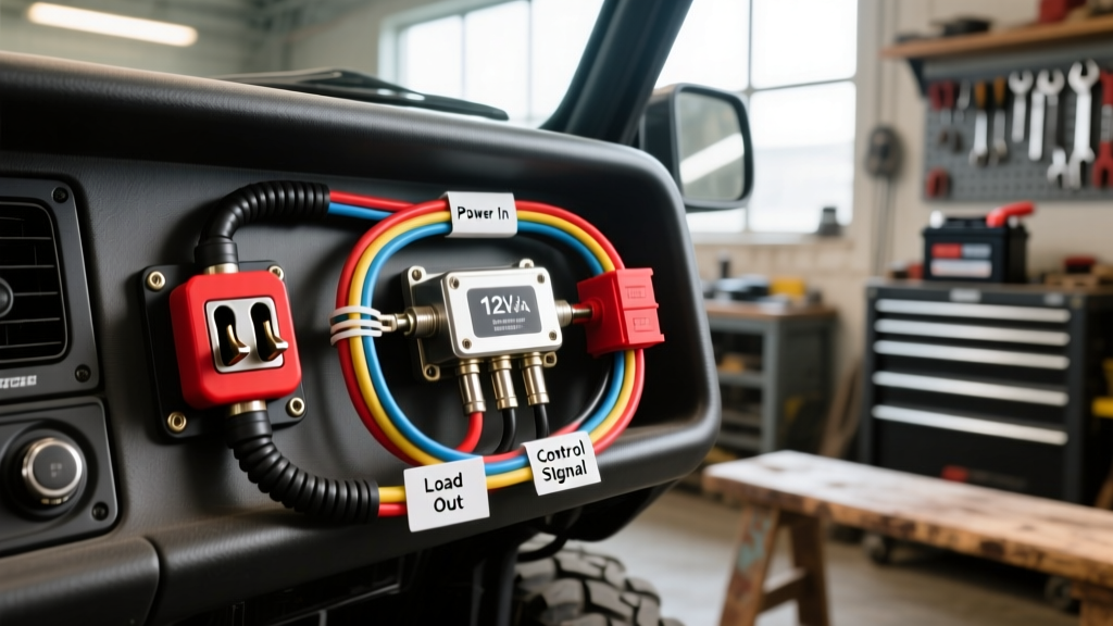
Understanding the Two Prong Rocker Switch (SPST) in Automotive Mods
When executing an upgrade or modification project—such as installing a 50-inch off-road LED light bar, a winch solenoid, or an onboard air compressor—the two prong rocker switch is the most common user interface selected for the cabin. Electrically, a standard two prong switch is a Single Pole Single Throw (SPST) device. It features a simple ON-OFF mechanism that either breaks or completes a single 12V DC circuit. Premium options, like the Carling V-Series Contura switches, are sealed to IP68 standards, making them ideal for open-top Jeeps, marine applications, and dusty overland builds.
However, the simplicity of the two prong design often leads amateur installers into a critical wiring trap: attempting to route high-amperage loads directly through the switch contacts. This guide details the exact methodology for integrating a two prong rocker switch into a high-current 12V automotive circuit using a Bosch-style relay, ensuring SAE-compliant safety, minimal voltage drop, and long-term reliability.
The Indicator Light Trap: Series vs. Parallel Wiring
Before cutting any wire, you must verify the internal architecture of your two prong rocker switch. Many cheap, imported SPST switches feature an internal 12V LED indicator light wired in series across the two prongs. This design relies on the resistance of the downstream load to complete the circuit to ground and illuminate the bulb.
The Failure Mode: If you wire a series-LED two prong switch to the control coil of a standard 30A automotive relay (Pin 85 and 86), the relay coil draws only about 150mA. This low current is insufficient to illuminate the switch's internal LED. Worse, the internal resistor for the LED will cause a severe voltage drop, delivering only 6V to 8V to the relay coil. The relay will either fail to pull in, or it will "chatter" rapidly, burning out the coil and melting the switch contacts.
The Expert Solution: For relay-triggered modifications, you must use either a two prong switch without an indicator light, or upgrade to a three prong switch (SPST with an independent parallel LED ground). If you are committed to using an illuminated two prong switch, the indicator light must be incandescent, and you must wire a dummy load (like a 470-ohm 5W resistor) in parallel with the relay coil to draw enough current to light the bulb without dropping the coil voltage below the 9V pull-in threshold.
Required Components and Wire Specifications
Adhering to SAE J1128 standards for low-tension primary cable is non-negotiable for under-hood and cabin routing. Never use Consumer Electronics (CCA) wire for automotive modifications; always use pure copper stranded wire with automotive-grade insulation.
| Component | Specification | Purpose & Technical Notes |
|---|---|---|
| Switch Circuit Wire | 18 AWG TXL (Cross-linked) | Carries low current (approx. 150mA) to the relay coil. TXL insulation resists heat and abrasion up to 125°C. |
| Load Circuit Wire | 12 AWG SXL or GXL | Carries high current (up to 20A continuous) from the relay to the off-road lights. Thicker insulation for under-hood routing. |
| Automotive Relay | Bosch-style 4-Pin, 30A | Isolates the high-current load from the cabin switch. Pins: 30 (Power In), 87 (Power Out), 85 (Ground), 86 (Switch In). |
| Inline Fuse | 20A ATO/ATC Blade | Protects the 12 AWG load wire. Placed within 18 inches of the battery positive terminal. |
| Fuse Tap | Micro2 or ATM Add-A-Circuit | Provides a switched 12V ignition source for the rocker switch without splicing factory harnesses. |
| Terminals | Nylon Insulated Ring/Spade | Use ratcheting crimpers. Never solder automotive wire; solder wicks under insulation and creates a brittle stress-riser point. |
Step-by-Step: Wiring the Two Prong Rocker Switch with a Relay
For this modification, we are wiring a 140W LED light bar (approx. 11.5A draw at 14.4V) controlled by a two prong SPST rocker switch mounted in a switch pod on the dashboard.
Step 1: Preparing the Switch Control Circuit (18 AWG)
- Find a Switched 12V Source: Locate an ignition-switched fuse in the cabin fuse box (e.g., the 12V accessory socket or radio fuse). Use a circuit tester to verify power is only present when the key is in the "RUN" position.
- Install the Fuse Tap: Insert the Add-A-Circuit fuse tap. Run an 18 AWG TXL wire from the tap to the dashboard switch pod.
- Connect to Switch Prong 1: Crimp a female quick-disconnect terminal onto the 18 AWG wire and attach it to one of the prongs on the back of the rocker switch. (On a standard SPST switch, polarity does not matter between the two prongs).
- Route to the Relay: Crimp another length of 18 AWG wire to the second switch prong. Route this wire through the firewall grommet to the engine bay where the relay will be mounted.
Step 2: Routing the High-Current Load Circuit (12 AWG)
According to expert consensus found in the The12volt Relay Guide, the relay acts as a heavy-duty remote switch. We will use 12 AWG wire for the high-draw side to prevent voltage drop over the 10-15 foot run to the front bumper.
- Pin 30 (Power In): Run a 12 AWG wire from the relay's Pin 30 terminal directly to the positive battery terminal. Critical: Install a 20A inline waterproof fuse holder within 8 inches of the battery post to protect against short circuits.
- Pin 87 (Power Out): Run a 12 AWG wire from Pin 87 to the positive input of your off-road LED light bar.
- Ground the Load: Run a 12 AWG wire from the negative input of the light bar to a clean, bare-metal chassis ground. Use a star washer to bite through the paint and ensure a zero-resistance connection.
Step 3: Completing the Relay Control Circuit
- Pin 86 (Switch In): Connect the 18 AWG wire coming from the second prong of your two prong rocker switch to Pin 86 on the relay.
- Pin 85 (Ground): Run a short 18 AWG wire from Pin 85 to a local chassis ground in the engine bay.
Advanced Termination and Weatherproofing
The vibration profile of an off-road vehicle will quickly destroy poorly terminated connections. For the two prong rocker switch connections, use fully insulated female spade connectors. Before crimping, strip exactly 5/16" of wire insulation. Use a ratcheting crimp tool calibrated for 22-18 AWG insulated terminals. The crimp should feature a dual-crimp profile: one barrel compressing the copper strands, and the rear barrel compressing the wire jacket for strain relief.
For all under-hood connections, slide a piece of dual-wall adhesive heat shrink tubing over the wire before crimping. Once crimped, apply heat until the tubing shrinks and the inner adhesive layer melts and extrudes slightly from the ends. This creates a waterproof, corrosion-proof seal that blocks battery acid fumes and road salt.
Troubleshooting Common Switch and Relay Failures
If your modification fails to operate, do not immediately suspect the rocker switch. Use a digital multimeter (DMM) to perform the following diagnostic sequence:
- Symptom: Switch clicks, but lights do not turn on.
Diagnosis: Measure voltage at Pin 87 of the relay with the switch ON. If you read 12.6V at Pin 87 but 0V at the light bar, you have an open circuit (broken wire) or a blown inline fuse between the relay and the lights. If you read 12.6V at the light bar's positive connector but it won't light, check the chassis ground for continuity. - Symptom: Switch gets hot to the touch.
Diagnosis: A hot switch indicates high resistance or an over-current condition. You have likely bypassed the relay and wired the load directly through the two prongs. Immediately disconnect the battery. The switch contacts are arcing and will eventually melt, causing a potential electrical fire. - Symptom: Relay chatters or clicks rapidly.
Diagnosis: This is a classic voltage drop issue. Check for a loose ground on Pin 85, or verify that the switched 12V source (fuse tap) is not overloaded. If the fuse tap is sharing a circuit with the ECU or fuel pump, the voltage will sag when the relay coil pulls in, dropping the voltage below the relay's holding threshold.
Final Inspection and Maintenance
Once the two prong rocker switch wiring is complete, perform a voltage drop test across the switch itself. Place your multimeter's red probe on the switch's input terminal and the black probe on the output terminal while the circuit is active. A healthy SPST switch should show a voltage drop of less than 0.05V. Anything higher indicates internal contact resistance, requiring switch replacement. By utilizing a relay, proper AWG sizing, and SAE-compliant materials, your custom off-road modification will operate flawlessly through thousands of miles of harsh terrain.