Why Overlanders Steal from the Marine Industry
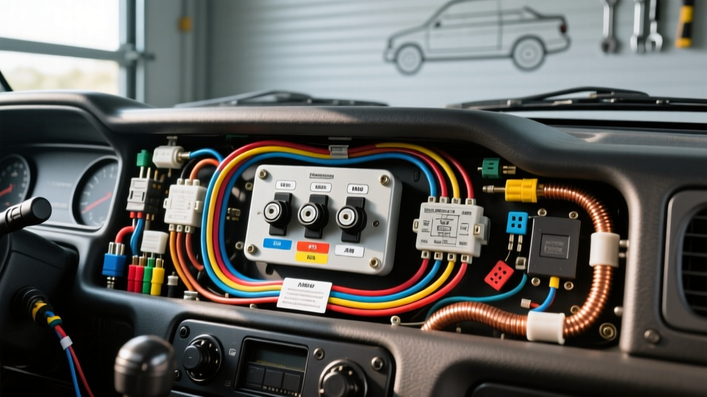
When building a custom overland truck, expedition rig, or dedicated off-road vehicle, standard automotive switch panels rarely survive the punishment of high-vibration trails, water crossings, and extreme temperature fluctuations. This is why seasoned fabricators and automotive electricians frequently turn to marine-grade components. If you have ever searched for a boat switch panel wiring diagram to use as a template for your 4x4's auxiliary lighting, winch controls, and onboard air compressors, you are not alone. Marine electrical topologies are designed for harsh, wet, and corrosive environments, making them inherently superior for severe-duty automotive applications.
However, adapting a traditional boat switch panel wiring diagram requires translating ABYC (American Boat and Yacht Council) standards into SAE (Society of Automotive Engineers) realities. Marine vessels utilize isolated ground returns to prevent galvanic corrosion, whereas automotive chassis grounds are standard. Furthermore, marine systems often rely on heavy-duty continuous solenoids rather than standard Bosch-style ISO mini relays. This guide will bridge the gap between marine schematics and automotive execution, providing a comprehensive product comparison, wire sizing matrix, and exact pinout configurations to ensure your custom installation is bulletproof.
Top Marine-Grade Switch Panels Compared for Automotive Use
Before cutting into your vehicle's harness, you must select the right control interface. Below is a technical comparison of the three most common switch panel architectures used in high-end off-road builds.
| System Architecture | Blue Sea 4x4 / Marine Panels | Switch-Pros SP9100 | Custom Carling V-Series Rockers |
|---|---|---|---|
| Switching Mechanism | Physical mechanical rockers triggering external relays | Solid-state semiconductor switching (no moving parts) | Individual mechanical rockers with integrated LEDs |
| Max Amperage per Circuit | Typically 20A (Relay dependent) | Up to 35A per circuit (Solid State) | 20A nominal (requires relays for >10A loads) |
| Wiring Complexity | High (requires separate relay block and heavy feed wires) | Low (Brain box handles switching; only thin trigger wires to panel) | High (individual power, ground, and illumination wires per switch) |
| Vibration Resistance | Excellent (IP67 rated external relays) | Superior (No mechanical contacts to arc or bounce) | Good (Internal detents can wear under extreme high-G loads) |
| Best Application | Budget-conscious builds using heavy marine relays | Premium overland rigs requiring programmable logic and sequencing | Custom dash integrations and OEM+ aesthetic replacements |
Decoding the Boat Switch Panel Wiring Diagram for 12V DC Automotive
When you pull up a standard boat switch panel wiring diagram, you will notice several distinct differences from a typical automotive Haynes or Chilton manual. Understanding these differences is critical to preventing voltage drops and parasitic draws in your truck.
1. The Grounding Topology: Isolated vs. Chassis
In marine applications, the ABYC E-11 standard mandates that all DC negative returns must be wired back to a centralized negative bus bar, which is then tied to the battery negative. This prevents stray current from traveling through the water or the hull. In an automotive application, the steel chassis is used as the ground return. Expert Advice: When adapting a marine diagram for an off-road truck, keep the marine isolated ground topology for your switch panel and auxiliary fuse block. Off-road vehicles suffer from chassis flex, paint thickness, and rust, all of which create high-resistance ground points. Run a dedicated 10 AWG or 8 AWG ground wire from your switch panel's negative bus directly to the vehicle's battery negative terminal or a known clean engine block ground.
2. Solenoids vs. ISO Relays
Marine diagrams frequently utilize heavy-duty continuous-duty solenoids (like the Blue Sea 9012) to manage high-amperage bus feeds, rather than switching individual circuits with 40A Bosch relays. For automotive auxiliary panels, a hybrid approach is best. Use a marine solenoid triggered by an ignition-switched source to power a centralized ST Blade fuse block, then use standard ISO mini relays switched by your panel's rocker switches for individual loads like LED light bars and air compressors.
Wire Sizing: SAE J1128 vs. ABYC Standards
Marine wire (UL 1426) is tinned to resist corrosion and features a higher strand count for flexibility, while automotive wire (SAE J1128, typically GXL or TXL cross-linked polyethylene) features a thinner insulation jacket for tighter routing. Because marine wire insulation is rated differently and engine bays experience higher ambient temperatures, you must adjust your AWG sizing when translating a boat switch panel wiring diagram to an under-hood automotive environment.
| Circuit Load (Amps) | SAE Auto Wire Size (Engine Bay) | ABYC Marine Wire Size (Cabin) | Recommended Fuse (ATO/ATC) |
|---|---|---|---|
| 5A - 10A | 16 AWG (GXL) | 14 AWG (Tinned) | 10A or 15A |
| 11A - 20A | 12 AWG (GXL) | 10 AWG (Tinned) | 20A |
| 21A - 30A | 10 AWG (GXL) | 8 AWG (Tinned) | 30A |
| Main Panel Feed (50A) | 6 AWG (GXL) | 4 AWG (Tinned) | 50A MIDI / ANL |
Note: Always size the fuse to protect the smallest wire in the circuit, not the load itself. For comprehensive wire ampacity charts, refer to the American Boat and Yacht Council (ABYC) standards or the SAE J1128 specification.
Carling V-Series Rocker Switch Pinout Configuration
If you are building a custom panel using Carling V-Series Contura rockers (the industry standard for both marine and high-end off-road panels), the wiring diagram can look intimidating due to the 8-pin configuration. Most automotive enthusiasts only need to understand three of these pins for basic switching, but utilizing the illumination pins correctly is what gives your rig a professional, OEM-level finish.
| Pin Number | Function | Recommended Wire Color | Wire Size |
|---|---|---|---|
| Pin 1 | Ground for Upper LED (Indicator) | Black | 18 AWG |
| Pin 2 | Output to Load (Switched 12V+) | Red or Blue | 14 AWG |
| Pin 3 | Input 12V+ (Constant or Ignition) | Red | 14 AWG |
| Pin 4 | Ground for Lower LED (Lens Illumination) | Black | 18 AWG |
| Pin 7 | Illumination 12V+ (Dash Light Trigger) | Orange or White | 18 AWG |
| Pin 8 | Internal Jumper / Not Used | N/A | N/A |
Wiring the Illumination Circuit
To ensure your switch panel dims with your vehicle's factory dashboard lighting, you must tap into the OEM headlight switch illumination circuit. Use a Blue Sea Systems Add-A-Circuit fuse tap or splice into the factory dash harness using a Posi-Tap connector. Route this 18 AWG Orange/White wire to Pin 7 on every switch, and daisy-chain Pin 1 and Pin 4 to your isolated negative bus bar. When the headlights turn on, Pin 7 receives 12V, illuminating the lower lens. When you flip the rocker to the 'ON' position, Pin 2 outputs 12V to your relay coil, and the upper indicator LED lights up via Pin 1.
Step-by-Step: Adapting the Diagram to Your Truck's Fuse Box
- Mount the Centralized Bus Bars: Install a positive and negative terminal bus bar in a protected area of the engine bay or under the dash. Do not mount the negative bar to painted sheet metal; bolt it directly to a clean, bare metal chassis point or run it to the battery.
- Run the Main Feed: Pull 6 AWG GXL wire from the vehicle's battery positive terminal to the positive bus bar. Install a 50A ANL or MIDI fuse within 6 inches of the battery terminal to protect against dead shorts.
- Wire the Solenoid (Optional but Recommended): If you want the entire panel to shut off when the key is removed, wire a continuous-duty solenoid between the battery and the positive bus bar. Trigger the solenoid's coil using an ignition-switched 12V source from the fuse box.
- Connect the Switch Panel: Run a 10 AWG red wire from the positive bus bar to Pin 3 on your first Carling rocker switch. Use 14 AWG jumper wires with heat-shrink butt splices to daisy-chain Pin 3 across all switches in the panel.
- Wire the Relay Coils: Run 14 AWG wire from Pin 2 (Output) of each switch to Pin 86 on your Bosch-style ISO relays. Connect Pin 85 on the relays to the negative bus bar.
- Wire the High-Current Loads: Connect Pin 30 on the relays to the positive bus bar (fused appropriately for each load). Connect Pin 87 to the positive terminal of your auxiliary lights, compressors, or lockers using Deutsch DT connectors for waterproof, vibration-proof terminations.
Real-World Troubleshooting: Marine vs. Auto Grounding Issues
Even when you follow a boat switch panel wiring diagram perfectly, integrating marine logic into an automotive charging system can yield unique electrical gremlins. Use this diagnostic tree to resolve common issues:
Symptom: Alternator Whine in Audio System or LED Flickering
- Cause: Ground loop created by mixing chassis grounds with isolated bus bar grounds.
- Fix: Ensure the switch panel's negative bus bar is tied only to the main negative bus bar or battery, not bolted to random dash brackets. Verify all audio amplifiers share the exact same ground reference point.
Symptom: Switch Illumination Stays On When Vehicle is Off
- Cause: Pin 7 (Illumination trigger) was wired to a constant 12V+ source instead of the OEM dash illumination circuit, or a back-feed is occurring through the CAN-bus system.
- Fix: Use a multimeter to verify Pin 7 drops to 0V when the headlight switch is turned off. If wired to a modern CAN-bus lighting circuit, install a standard 1N4001 diode on the trigger wire to prevent back-feeding voltage from the vehicle's BCM (Body Control Module).
Symptom: Voltage Drop at the Load (Lights are dim)
- Cause: Using undersized wire for the distance, or relying on a poor chassis ground for the load itself.
- Fix: Measure voltage at the relay Pin 87, then measure at the load. If there is a drop greater than 0.5V, upgrade the wire gauge. For high-draw loads like onboard air compressors, always run a dedicated ground wire back to the negative bus bar rather than trusting the compressor's mounting bolts to ground to the chassis.
By respecting the robust engineering behind marine electrical schematics while adapting them to the specific vibration and grounding realities of automotive platforms, your custom switch panel installation will deliver reliable, weatherproof performance for years on the trail.